AMETEK Lx Series II User Manual
Page 56
User Manual
Lx / Ls Series II
52
Connector
SMA Connectors
Discrete Fault Indicator
Remote Inhibit
Trigger Out1
(Function Strobe)
Trigger In1
RPV (N/A)
BNC Connectors
Clock
Table 3-6 -LKM / -LKS option
Lock
Ls Series
Other
Function
Table
SMA Connectors
Discrete Fault Indicator
J7-36+ / J7-27-
(Remote Shutdown)
Function Strobe
Trigger
RPV (N/A)
BNC Connectors
J1 - Clock
Table 3-6 -LKM / -LKS option
J2 - Lock
Table 3-2: Rear Panel Connectors
3.6.1 AC Input Connector
– INPUT
See section 3.4 for details on connecting AC input power. Labeled INPUT on Lx models, INTPUT
TB3 on Ls models.
INPUT.
Designator
Lx Series
Designator
Ls Series
Direction
Connection
Description
1
L1
ØA
Input
AC Line
2
L2
ØB
Input
AC Line
3
L3
ØC
Input
AC Line
4
GND
Gnd symbol
Chassis Ground
Table 3-3: AC Input Terminal Block Connection Description
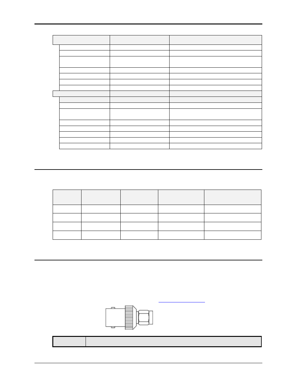
3.6.2 SMA Connectors
– Lx Series
SMA connectors. Functions are called out on rear panel decal. Table 3-4 shows connections
from left to right when standing at the rear of the Lx cabinet. SMA connectors are small high
frequency capable coax connectors that can be screwed down securely to prevent signal loss.
Adaptor for SMA to BNC conversion are readily available.
To connect these signals using more conventional BNC cables, SMA Male to BNC Female
adapters may be used. These are available from
, P/N PE9074.
PE9074 Adaptor.
SMA
Description