Adept s650HS Quattro User Manual
Page 95
Chapter 5: System Operation
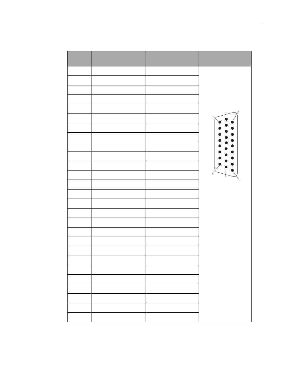
Table 5-8. XIO Breakout Cable Wire Chart
Pin No.
Signal
Designation
Wire Color
Pin Locations
1
GND
White
Pin 9
Pin 1
Pin 18
Pin 10
Pin 19
Pin 26
26-pin male
connector on XIO
Breakout Cable
2
24 VDC
White/Black
3
Common 1
Red
4
Input 1.1
Red/Black
5
Input 2.1
Yellow
6
Input 3.1
Yellow/Black
7
Input 4.1
Green
8
Input 5.1
Green/Black
9
Input 6.1
Blue
10
GND
Blue/White
11
24 VDC
Brown
12
Common 2
Brown/White
13
Input 1.2
Orange
14
Input 2.2
Orange/Black
15
Input 3.2
Grey
16
Input 4.2
Grey/Black
17
Input 5.2
Violet
18
Input 6.2
Violet/White
19
Output 1
Pink
20
Output 2
Pink/Black
21
Output 3
Light Blue
22
Output 4
Light Blue/Black
23
Output 5
Light Green
24
Output 6
Light Green/Black
25
Output 7
White/Red
26
Output 8
White/Blue
Shell
Shield
Adept Quattro User's Guide, Rev F
Page 95 of 196
This manual is related to the following products: