2 adept quattro internal connections, 3 xsys/xsystem connector – Adept s650HS Quattro User Manual
Page 119
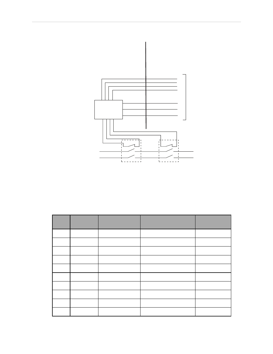
Chapter 7: Technical Specifications
7.2 Adept Quattro Internal Connections
Quattro AIB/eAIB
Internal Connections
Quattro Panel
Connections
Force-Guided Relay
Cyclic Check
Control Circuit
Force-Guided
Force-Guided
Single-Phase
AC Input
200-240 VAC
High Power to
Amplifiers
Man 1
Man 2
Auto 1
Auto 2
XSLV-2 (XSYSTEM 8)
XSLV-3 (XSYSTEM 38)
XSLV-6 (XSYSTEM 14, 29)
XSLV-7 (XSYSTEM 30, 44)
ESTOPSRC
ESTOPGND
HPWRREQ
XSLV-9 (XSYSTEM 16)
XSLV-1 (XSYSTEM 17)
XSLV-5 (XSYSTEM 34)
To XSYS on
SmartController
Figure 7-10. Robot Internal Connections Diagram
7.3 XSYS/XSYSTEM Connector
Table 7-2. XSYS to XSYSTEM Connector Pinouts (eAIB only)
XSYS
Pin #
XSYSTEM
Pin #
Description
Comment
Pin Location
1
17
ESTOP_GND
E-Stop system Ground
2
8
ENABLE_SW_1-
3
38
ENABLE_SW_2-
4
15
HPWR_DIS
High Power Disable
5
34
HPWR_REQ
6
14 & 29
MUTE_GATE_1-
7
30 & 44
MUTE_GATE_2-
8
N/C
9
16
ESTOP_SRC
E-Stop System +24 V
Shell
Shell
SHIELD
Adept Quattro User's Guide, Rev F
Page 119 of 196