0 dimensions and clearances, 1 clearances, Minimum clearances from combustible material – Reznor SHH (Indoor PreevA) Unit Installation Manual User Manual
Page 7: Recommended service clearances by model and size
Form I-PDH/SDH/PEH/SHH/PXH, Page 7
Other Field-Installed Accessories
4.1 Clearances
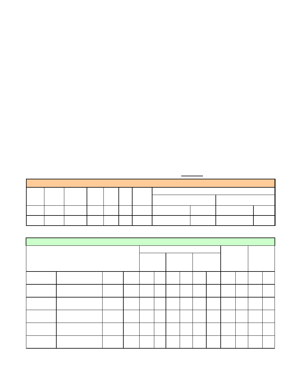
For safety and convenience, provide clearances as shown in
TABLE 2 and TABLE 3.
Clearance to combustibles is defined as the minimum distance from the heater to a
surface or object that is necessary to ensure that a surface temperature of 90°F above
the surrounding ambient temperature is not exceeded. Minimum clearances are also
listed on the heater rating plate.
Minimum Clearances from Combustible Material
Control
Side
Opposite
Control
Side
Front Rear Top Bottom
Gas-Fired Models
Vent Connector at Unit
Vent Pipe
inches
20
6
48
18
6
0
PDH/SDH - 18
SHH - 6
PDH/SDH - 6
SHH - 0
mm
508
152
1219
457
152
0
PDH/SDH - 457 SHH - 152 PDH/SDH -152 SHH - 0
TABLE 2 - Minimum Clearance from Combustibles - applies to All Sizes
Recommended Service Clearances by Model and Size
Model and Size
Control Side
Side
Opposite
Controls
Top
Control Side
(Basic)
Control Side
with Mixing
Box
Control Side
with Cooling
Coil*
SDH and PDH
PEH
SHH
PXH
inches mm inches mm inches mm
inches mm inches mm
75, 100
10A, 20A, 40A
N/A
000A
30
762
30
762
42
1067
6
152
18
457
125, 150
15B, 30B, 60B
N/A
000B
34
864
34
864
52
1321
6
152
18
457
175, 200, 225
N/A
130, 180 000C
30
762
30
762
42
1067
6
152
24
610
250, 300
30D, 60D, 90D, 120D
260
000D
42
1067 42
1067
58
1473
6
152
24
610
350, 400A
40E, 80E, 120E
350
000E
52
1321 52
1321
66
1676
6
152
24
610
TABLE 3 - Service Clearances
4.0 Dimensions
and Clearances
Storage and Startup
If this system is going to be stored, take precautions to prevent condensate formation
inside the electrical compartments and motors. To prevent damage to the unit, do not
store sitting on the ground.
After the system has been moved to its installation site, remove all of the shipping
brackets and check all of the fans for free movement. See the check lists in Paragraph
9.0 before starting the unit and completing the Startup Form.
* Clearance is required to remove slide out drain pan.
If your unit was ordered with Option UV2, UVC lights in the cooling coil module, the
bulbs and a box of parts are shipped in the blower compartment for field installation.
Being careful not to touch the bulbs, verify the components with the instruction sheet
included with the parts.
Before beginning installation, be sure that all shipped-separate options ordered are
available at the site. In addition to the vent/combustion air kit, field-installed, shipped-
separate options could include an energy recovery unit, a downturn nozzle, VFD, a
thermostat or other wall-mounted control, a remote console, a disconnect switch, fill
and drain kit, water hammer arrestor, firestat, a vent cap, and/or a smoke detector.