0 mechanical (cont’d), 4 optional mixing box) (cont’d), Operating sequence with economizer option – Reznor SHH (Indoor PreevA) Unit Installation Manual User Manual
Page 28: 3 mixing box damper and control options (cont’d)
Form I-PDH/SDH/PEH/SHH/PXH, Page 28
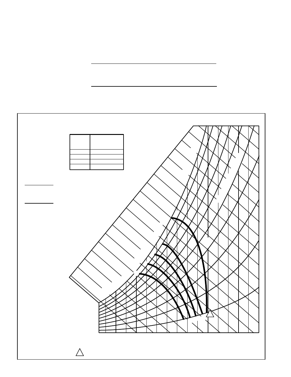
FIGURE 20B - Partial Psychometric Chart for Setting
Economizer Logic Module (Reprinted with permission from
Honeywell)
CONTROL
CURVE
A
B
C
D
CONTROL POINT
APPROX. °F (°C)
AT 50% RH
73 (23)
70 (21)
67 (19)
63 (17)
12
14
16
18
20
22
24
26
28
30
32
34
36
38
40
42
44
46
90
10
0
80
70
60
50
40
30
20
10
ENTHALPY—BTU PER POUND DR
Y AIR
85
(29)
90
(32)
95
(35)
100
(38)
105
(41)
110
(43)
35
(2)
35
(2)
40
(4)
40
(4)
105
(41)
110
(43)
45
(7)
45
(7)
50
(10)
50
(10)
55
(13)
55
(13)
60
(16)
60
(16)
65
(18)
65
(18)
70
(21)
70
(21)
75
(24)
75
(24)
80
(27)
80
(27)
85
(29)
90
(32)
95
(35)
100
(38)
APPROXIMATE DRY BULB TEMPERATURE— °F (°C)
A
A
B
B
C
C
D
D
M11160C
RELA
TIVE HUMIDIT
Y
(%)
1
1
HIGH LIMIT CURVE FOR W7210D, W7212, W7213, W7214, W7340B.
•
Option GE21 - Use this
chart to set economizer
logic module.
•
Option GE22 - Set
economizer logic module
to “D” as shown on chart.
Operating Sequence with Economizer Option
Turn on the power and, if applicable, the gas.
On a call for low stage cooling:
1. The blower motor is energized.
2. With the outdoor enthalpy lower than the return air enthalpy:
a) The stage 1 and 2 cool circuits are locked out.
b) Dampers are positioned by the economizer and
mixed air sensor.
3. With outdoor air enthalpy higher than the return air enthalpy:
a) The stage 1 cool circuit is energized.
b) Dampers are positioned for minimum outside air.
c) On a call for high stage cooling, the stage 2 and 3 circuits are staged
appropriately
6.4.4.3 Mixing Box Damper and Control Options (cont’d)
6.4.4 Optional Mixing Box) (cont’d)
6.0 Mechanical
(cont’d)