3 combustion air requirements - model pdh – Reznor SHH (Indoor PreevA) Unit Installation Manual User Manual
Page 21
Form I-PDH/SDH/PEH/SHH/PXH, Page 21
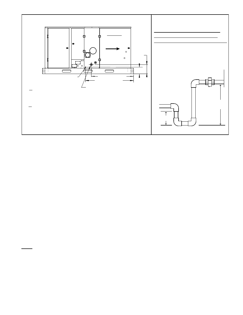
FIGURE 12 - Location of Condensate Drain Connections on a
Model SHH heat section
Minimum Dimensions for Secondary
Heat Exchanger Condensate Drain
Trap Required on all Model SHH Heaters
“A” = 3 inches (76mm) minimum
“B” = “A” plus at least 5 inches
(127mm)
Use 1/2” PVC pipe or larger
for condensate drain.
Drain Trap
Continue into
sanitary drain.
“A”
“B”
39-1/2” (1003mm)
44-5/8” (1133mm)
Secondary Heat Exchanger
Condensate Drain with 1/2” PVC
connection on all Model SHH units -
All Model SHH units require a
condensate drain with a trap as
illustrated in
FIGURE 13.
Burner Condensate Drain
with 1/2” NPT connection
on all Model SHH heaters
-- IF the system includes a cooling
module, Option AU, install a
drain line with a trap as
illustrated in
FIGURE 11.
-- IF the system does not include a
cooling module, cap this connection.
Side View
Model SHH
Airflow
8-13/16”
(224mm)
6-7/8”
(175mm)
FIGURE 13 - Secondary Heat
Exchanger Drain Trap - Model SHH
NOTES: See Vent Manual, Form I-SHH-V, for detailed information on
installing the vent pipe condensate drain.
If the system includes a cooling coil cabinet, the cooling coil cabinet also
requires a condensate drain. See Paragraph 6.6.3
Condensate Drain
Traps
A condensate drain trap is required for
each condensate drain line.
•
FIGURE 11 illustrates the trap in the drain attached to the burner and lists the
minimum required leg dimensions for that trap.
•
FIGURE 13 illustrates the secondary heat exchanger drain trap and lists the
required length difference for the trap legs.
The most important part of fabricating and assembling the traps is the length of the
individual legs of the traps. If the difference in the lengths of the legs of the traps is not
as illustrated, it could prevent proper drainage of the condensate and possibly permit
vent gas to enter the building. (The length difference is also what provides a “water
seal” that prevents leakage of vent gas into the sanitary drain.) The two traps may be
drained into a common pipe that is connected to the sanitary drain.
The orientation of the piping is not critical and may be arranged to suit the installation.
Unions are recommended to permit maintenance of the drains and to facilitate service
of the heater. A union is shown in both of the traps and a third union is recommended
in the drain pipe. If pipe insulation or heat tapes are required to prevent freezing, use
should be in accordance with generally accepted plumbing practices.
NOTES:
If the system has a cooling
coil, the cooling coil
cabinet will also require
a condensate drain;
see Paragraph 6.6.3 for
requirements.
A Model SHH has a
condensate drain on the
vent pipe; see Form
I-SHH-V for details.
6.3 Combustion Air
Requirements -
Model PDH
A Model PDH heater must be supplied with the air that enters into the combustion
process and is then vented to the outdoors. Combustion air enters through the com-
bustion air opening on the side of the unit and comes from the equipment location.
Sufficient air must enter the equipment location to replace that exhausted through
the heater vent system. In the past, the infiltration of outside air assumed in heat loss
calculations (one air change per hour) was assumed to be sufficient. However, current
construction methods using more insulation, vapor barriers, tighter fitting and gasketed
doors and windows, weather-stripping, and/or mechanical exhaust fans may require
the introduction of outside air through wall openings or ducts.
The requirements for combustion and ventilation air depend upon whether the unit
is located in a confined or unconfined space. An “unconfined space” is defined as a
space whose volume is not less than 50 cubic feet per 1000 BTUH of the installed
appliance.
Under ALL conditions, enough air must be provided to ensure there will
not be a negative pressure condition within the equipment room or space.
NOTE: For both Model
SDH and SHH, combustion
air must be ducted from
outside through the vent/
combustion air terminal
kit shipped with the unit.
See the Venting Manual,
Form I-SDH-V or Form
I-SHH-V, for combustion air
requirements.