0 mechanical (cont’d), 7 unit discharge (cont’d), 5 hot water heat module, option hw2 - pxh only – Reznor SHH (Indoor PreevA) Unit Installation Manual User Manual
Page 40: Figure 34 - field- installed optional nozzles, Table 26a - dimensions
Form I-PDH/SDH/PEH/SHH/PXH, Page 40
6.7.4 Optional
Discharge Nozzles
with Horizontal
Louvers - Models
PDH, SDH, & SHH
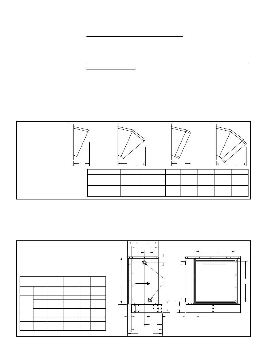
Follow the illustrated instructions shipped with the option package to install
the nozzle options. Depending on which option was ordered, the nozzle will
have the downturn range shown in
FIGURE 34, with or without vertical louvers.
NOTES: Discharge nozzle options do not apply to electric heat Model PEH or to “no
heat” Model PXH. See Paragraph 6.7.5 for optional nozzles for Model PXH with hot
water heat.
FIGURE 34 -
Field-
Installed
Optional
Nozzles
Z
With 25-65°
downturn
nozzle with
horizontal
louvers
(Option
CD2)
With 50-90°
downturn
nozzle with
horizontal
louvers
(Option
CD3)
Z
Z
With 25-65°
downturn
nozzle with
horizontal
and vertical
louvers
(Option
CD4)
With 50-90°
downturn
nozzle with
horizontal
and vertical
louvers
(Option
CD5)
Z
TABLE 25 - Additional
Length of Optional
Discharge Nozzles,
Dimension Z (inches & mm)
PDH/SDH Sizes
SHH Size PXH (no heat) Option
CD2
CD3
CD4
CD5
75, 100, 125, 150
N/A
000A, 000B
inches
9
15-11/16
12-1/2
17-3/4
mm
229
398
318
481
175, 200, 225, 250,
300, 350, 400A
130, 180,
260, 350
000C, 000D,
000E
inches
13-9/16
23-5/8
17-1/8
25-11/16
mm
345
600
435
652
6.7.5 Hot Water Heat
Module, Option HW2 -
PXH only
Airflow
19-1/8 (486)
16-3/4 (425)
3-1/2
(89)
A
Water Inlet
Water Outlet
7-11/16
(195)
2-5/16
(59)
7-9/16
(192)
11-1/8
(282)
19-1/8 (485)
21-3/8 (543)
6-3/4
(171)
6-1/4
(159)
D
C
B
Discharge Opening
(Standard opening;
with factory-installed Option
AX2, Horizontal Louvers,
Option AX3, Horizontal and
Vertical Louvers, or
Option AX4, Duct Flange;
or field-installed Option CD2
or CD3, Discharge Nozzles,
or Option CD3 or CD4,
Discharge Nozzles with
Horizontal and Vertical
Louvers
The optional hot water heat module is factory-installed on the unit base at the dis-
charge end of a Model PXH. The module was either ordered with a factory-installed
coil or the coil is field-supplied for installation at the job site.
Dimensions
FIGURE 35A - Dimensions
of Hot Water Heat Module,
Option HW2 - inches (mm)
The cabinet height and width are the same as the PXH; see Paragraph 4.2. See
FIG-
URE 35A for length and connection dimensions. Add the length of the module to the
PXH length in Paragraph 4.2.
PXH with HW2
A
B
C
D
000A
inches 29-3/8
3-3/4
25
24
mm
746
95
635
610
000B
inches 29-3/8
3-3/4
25
34
mm
746
95
635
864
000C
inches 35-9/16 2-15/16
35
24
mm
903
75
889
610
000D
inches 35-9/16 2-15/16
35
40-1/4
mm
903
75
889
1022
000E
inches 35-9/16 2-15/16
35
48-1/4
mm
903
75
889
1226
TABLE 26A - Dimensions
6.7.3 Discharge Air
Sensor for Makeup
Air Application
(cont’d)
6.7 Unit Discharge
(cont’d)
6.0 Mechanical
(cont’d)
3. The procedure for installing the sensor and attaching the holder depends on
whether the sensor is a capillary or an electrical sensor. Follow the instructions
that apply.
Capillary Sensor (Option AG2, AG3, and AG60) - Locate the sensor capillary
and run it out through the hole in the discharge panel of the heater. Remove the
knockout on the end of the box. Put the capillary through the hole and secure the
bulb to the clip in the holder. Attach the bracket to the box. Attach the bracket to
the front of the heater (
FIGURE 33).
Sensor with Wire (Options AG15, AG16, AG58, AG61, AG62, DG5, DG6, D12B,
D12C, D12F, and D12G) - Push the element into the clip in the holder. Determine
where the sensor wire should go through the box and remove the knockout at that
location. Attach a field-supplied cable connector to the box. Connect the sensor
wire. Attach the bracket to the box. Attach the bracket to the front of the heater.