3 cooling module condensate drain – Reznor SHH (Indoor PreevA) Unit Installation Manual User Manual
Page 35
Form I-PDH/SDH/PEH/SHH/PXH, Page 35
B
3/4 (19mm)
duct flange
3/4 (19mm)
duct flange
C
18-3/8
(467mm)
1 MPT
Drain
1-1/2 MPT
2-13/32(61mm)
1/4NPT Vent
27-3/4 (705mm)
D
1/4 NPT
Drain
2(51mm)
10-5/32
(2581mm)
12-21/64
(313mm)
14-21/64 (364mm)
17-47/64 (450mm)
Inlet Air
View
(with duct
flange*)
Side
View
3-3/32
(79mm)
NOTE: See
Paragraph
5.1, page 10,
for weights.
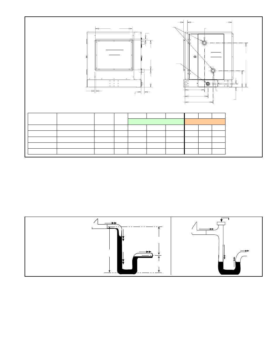
FIGURE 28 -
Chilled Water
Cooling
Coil Module
Dimensions
(no reheat)
Model PDH or
SDH
Model PEH
Model
SHH
Model
PXH
B
C
D
B
C
D
Dimensions (inches)
Dimensions (mm)
75, 100
10A/20A/40A
N/A
000A
22-7/8
10-19/32 27-9/32
581
269
693
125, 150
15B/30B/60B
N/A
000B
26-1/2
10-19/32 27-9/32
673
269
693
175, 200, 225 N/A
130, 180 000C
22-7/8
10-19/32 37-9/32
581
269
947
250, 300
30D/60D/90D/120D 260
000D
34-3/4
15-7/32
37-9/32
883
387
947
350, 400A
40E/80E/120E
350
000E
45-3/4
15-7/32
37-9/32
1162
387
947
TABLE 21 - Chilled Water Cooling Coil Module Dimensions
*If there is a mixing
box, the coil cabinet
will not have a duct
flange and this end
of the coil cabinet
will be attached to
the mixing box.
Drain Trap
To prevent air
from entering
always close
the cleanout.
Water Flow
Unit
FIGURE 29B -
Drain Trap with
Cleanout
B
A
A/2
C
L
C
L
C
L
Unit
Water Flow
Water Flow
A = 1” (25mm) for each 1”
(25mm) of maximum static
pressure plus 1” (25mm)
B = A + A/2
FIGURE 29A -
Condensate Drain
Trap Dimensions
6.6.3 Cooling Module
Condensate Drain
A removable drain pan with a 1” MPT drain connection is located below the coil cabinet
(See
FIGURE 27A or B or FIGURE 28). When connecting the drain line, provide a
means of disconnecting the line at or near the cabinet connection to allow the drain
pan to be removed for cleaning.
Ensure the system is level and
install a trap in the drain (see FIGURE 29A). Pitch the
drain line at least 1/2” (13mm) for every 10 feet (3M) of horizontal run. Drain lines must
not interfere with drain pan or access panels. An obstruction in the drain or a poorly
designed drain can cause the condensate pan to over flow which could result in unit
or building damage.
If the installation or local code requires, run drain into a waste water system.
The design of the drain trap is important. Since the condensate drain pan is on the
blower inlet side, there is a negative pressure at the drain relative to the ambient. The
trap height must account for this static pressure difference. Maximum negative static
can be determined by reading the negative pressure at the blower inlet and adding .2”
w.c. to allow for dirty filters.
If dimension “B” is not tall enough, the water seal will not hold and air will be drawn
through the drain pipe into the system. If the outlet leg of the trap is too tall, water will
back up into the drain pan. As condensate forms during normal operation, the water
level in the trap rises until there is a constant outflow.
FIGURE 29A illustrates the
appropriate dimensions for trapping a negative pressure system.
Improper trap design accounts for some condensate drainage system failures, but
incorrect use and maintenance of condensate drain traps can also cause problems.