Reznor SHH (Indoor PreevA) Unit Installation Manual User Manual
Page 27
Form I-PDH/SDH/PEH/SHH/PXH, Page 27
Enthalpy Sensor(s) -
Field installed to
control dampers in
economizer Options
GE21 and GE22) - PDH,
SDH, PEH, PXH, SHH
Option GE21 requires installation of one sensor; Option GE22 requires installation of
two sensors. A system with Option GE21 includes one field-installed parts bag. A sys-
tem with Option GE22 includes two field-installed parts bags. Locate the parts bag(s)
shipped inside the unit.
TABLE 18 - Components
in each Parts Bag, P/N
220686 (GE21 requires one
parts bag; GE22 requires
two.)
1. Turn off the power. Turn off the gas (Models PDH, SDH, SHH).
2. Install the Outside Air Enthalpy Sensor - Options GE21 and GE22
a)
Attach the Sensor in the Outside Air Ductwork
Position the sensor on the inside of the outside air ductwork. The sensor may
be mounted in any orientation but must be located so that it is exposed to freely
circulating air and must be protected from rain, snow, and direct sunlight. Position
the sensor in a central location and attach with the two screws provided.
b)
Wire the Sensor
Connect the two wires to the sensor as shown on the wiring diagram. Drill a 5/8”
hole in the outside air damper mounting frame as illustrated in
FIGURE 20A. Insert
the strain relief bushing. Bring the wires through the opening and route them to
the bottom of the electrical box. Use the stick-on wire holders to prevent the wires
from interfering with the damper operation. Insert a strain relief bushing in a hole in
the bottom of the electrical box and route the wires through. Make connections at
the economizer logic module as shown on the wiring diagram.
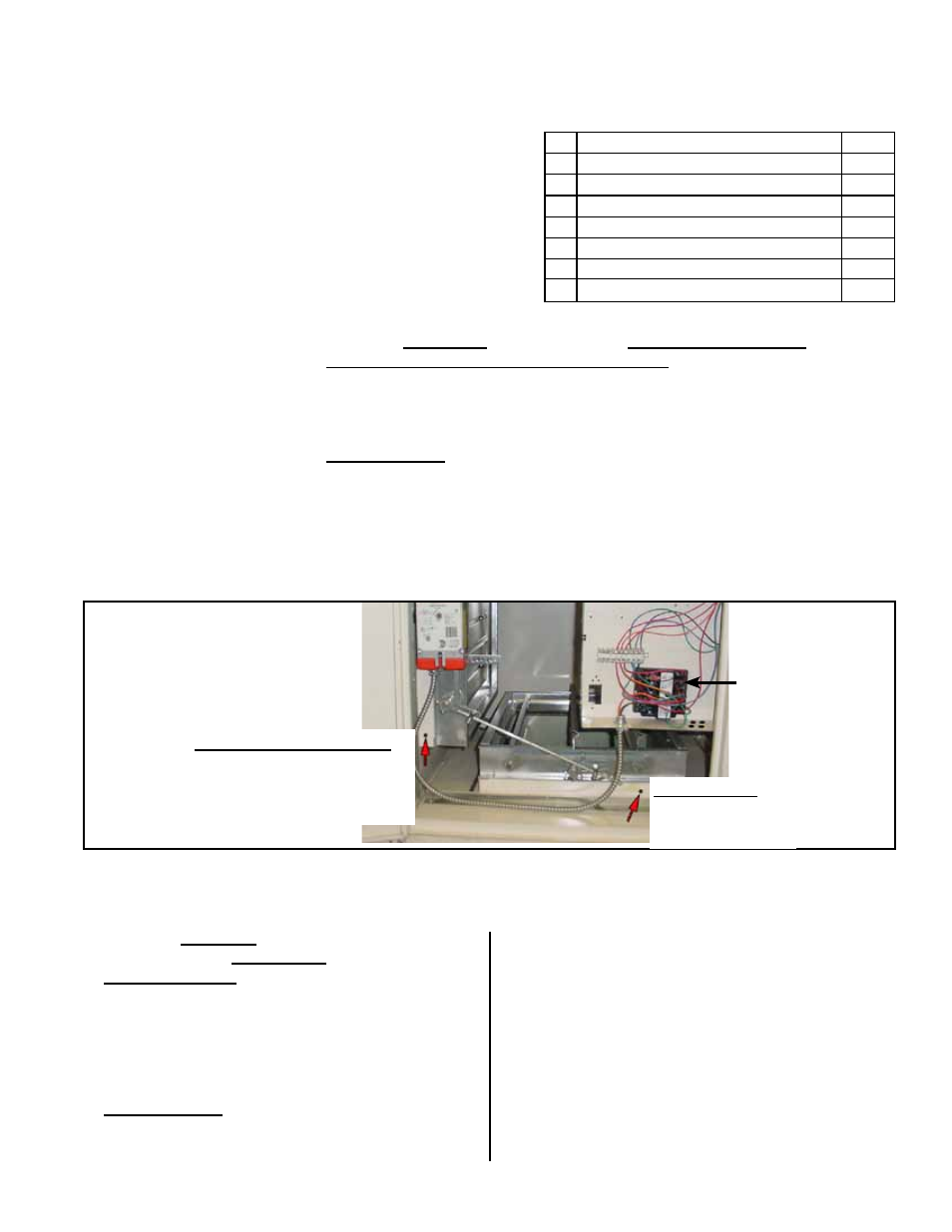
Options GE21 and GE22
- Drill a 5/8” hole in
the outside air damper
mounting frame.
Option GE22 - Drill a
5/8” hole in the return air
damper mounting frame.
Economizer
Logic Module,
P/N 220637
FIGURE 20A - Mixing Box
with Optional Economizer
Logic Module
3. Install the Return Air Enthalpy Sensor in the
Return Air Duct - Option GE22
a)
Attach the Sensor
Position the sensor on the inside of the return air
duct. The sensor may be mounted in any orientation
but must be located so that it is exposed to freely
circulating air. Position the sensor in a central location
on the side of the duct and attach with the two screws
provided.
b)
Wire the Sensor
Connect the two wires to the sensor as shown on
the wiring diagram. Drill a 5/8” hole in the return air
damper mounting frame as illustrated in
FIGURE
20A. Insert the strain relief bushing. Bring the wires
through the opening and route them to the bottom of
the electrical box. Use the stick-on wire holders and
the wire ties to prevent the wires from interfering with
damper operation. Insert a strain relief bushing in a
hole in the bottom of the electrical box and route the
wires through. Make connections at the economizer
logic module as shown on the wiring diagram.
Installation of Option GE22 is complete. Refer to
FIGURES 20B and 20C to set the economizer logic
module.
Enthalpy Control
Sensor Installation
Instructions
Installation of Option GE21 is complete. Refer to
FIGURES 20B and 20C to set the
economizer logic module.
If installing a return air sensor (Option GE22), continue to Step 3 (below).
Qty
Component Description
P/N
1
Enthalpy Sensor, Honeywell #C7400A1004
196290
1
Blue Wire Assy, 18 ga x 72” with terminals
220621
1
Purple Wire Assy, 18 ga x 72” with terminals
220620
2
Screws, #6 x 3/4” long
110650
2
5/8” Strain Relief, Heyco #SR6N-4
100392
4
Stick-on Wire Retainers, Fastex #8511-29-00
142678
2
Plastic Wire Ties
20913