0 electrical supply and wiring (cont’d), Cl33, Cl52 – Reznor SHH (Indoor PreevA) Unit Installation Manual User Manual
Page 46: Cl22, Cl36, Cl23, 4 control wiring (cont’d), 2 analog or digital controls (cont’d), Important, Shh w/ag58)
Form I-PDH/SDH/PEH/SHH/PXH, Page 46
If using an analog control system, use either an optional or a field-provided low-voltage
(24V) thermostat. (A thermostat is not supplied.) Install the thermostat according to the
manufacturer’s instructions. Depending on the control system option, select either a
single-stage or two-stage thermostat.
Analog Control System Requires an Optional or Field-Supplied
Thermostat
Digital Control Systems
have a Programmable
Unit-Mounted Control
and a Room Command
Module
If using a digital control system, the unit is factory equipped with a programmable
controller.
Digital control Options DG1, DG2, DG5, and DG6 also include a room command mod-
ule. The type of room command module depends on whether the control system has
a discharge or a room temperature controlled setpoint. A room command module with
an adjustable room temperature setpoint (45°F - 95°F) included with Option DG1 and
DG2 control systems is illustrated in
FIGURE 38. A room command module with a dis-
charge air setpoint included with Option DG5 and DG6 control systems is in
FIGURE
39. The discharge air setpoint can be adjusted ±6°. Discharge temperature controls
may also have an optional room-mounted override sensor.
IMPORTANT:
The digital controller inputs are low-current, resistance-based
signals. See special wiring recommendations above for digital sensor wiring.
Digital control Options D12B, D12C, D12D, D12E, D12F, and D12G do not include a
room command module. The space temperature sensor module with adjustable set-
point control and room override illustrated in
FIGURE 40 is available as an option.
NOTES:
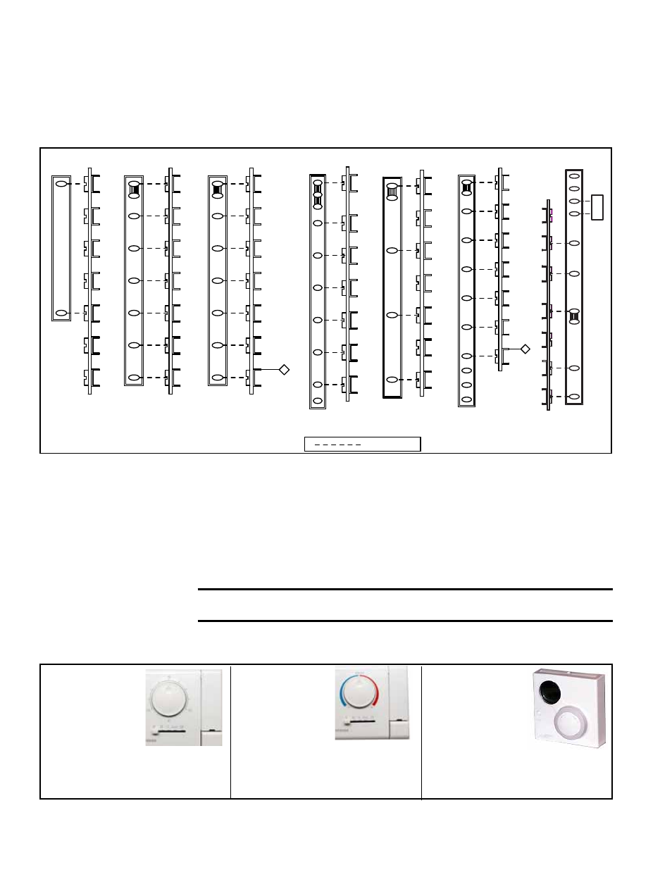
1) JUMPER THERMOSTAT TERMINALS RH TO RC.
FIELD WIRING
(USE
WITH AG2)
TWO ST
AGE HEA
T/COOL
THERMOST
AT W/F
AN SWITCH
(SEE NOTE #1)
G
W1
W2
Y2
Y1
RC
RH
RH
(SEE NOTE #1)
A1
G
W2
W1
Y2
Y1
X
A2
RC
G
W2
W1
Y2
Y1
C
R
TERMINAL
STRIP
G
W1
W2
Y2
Y1
C
R
TERMINAL
STRIP
CL33
P/N 221038
CL52
P/N 220632
CL22
P/N 220630
CL22
P/N 220630
SINGLE ST
AGE THERMOST
AT
TERMINAL
STRIP
G
W2
W
W1
Y2
Y1
C
R
R
CL1
P/N 255350
W2
TWO ST
AGE HEA
T/COOL
THERMOST
AT W/F
AN SWITCH
TERMINAL
STRIP
G
W2
G
Y1
(SEE NOTES #1
AND #2)
W1
Y2
W1
Y2
RC
RH
Y1
C
R
(RECIRCULATING AIR) (MAKE-UP AIR)
14
IN HEAT
SECTION
TERMINAL
BLOCK
G
W
Y
R
RC
(SEE NOTE #1)
G
W1
W2
Y2
Y1
C
TERMINAL
STRIP
R
SINGLE ST
AGE PROGRAMMABLE THERMOST
AT
TWO ST
AGE PROGRAMMABLE THERMOST
A
T
C
C
2) SET FAN CONTROL FUNCTION TO "ELECTRIC FURNACE".
BK
(Ref WD 226260)
CL36
(SHH w/AG58)
P/N 257600
CL23
(SHH only)
P/N 257338
IN HEAT
SECTION
TERMINAL
BLOCK
W2
TWO ST
AGE HEA
T/COOL
PROGRAMMABLE THERMOST
AT
TERMINAL
STRIP
G
W2
G
Y
W
Y2
W1
Y2
RC
R
Y1
C
R
14
C
BK
S2
S1
A
Y1
Y2
G
W1
R
W2
C
THERMOSTAT
TERMINAL
STRIP
(NOT IN
SEQUENCE)
X
RC
RH
W1
G
MX
MH
AS
AS
DISCHARGE
AIR SENSOR
Y1
(USE WITH
AG3,15,16,60,61,62)
PROGRAMMABLE MODULA
TING HEA
TING/COOLING
THERMOST
AT
(SEE NOTE #1.)
FIGURE 37 - 24V Wiring by Thermostat Option Code
FIGURE 38 -
Room Com-
mand Module,
P/N 211423,
Sensing Space
Temperature for
FIGURE 39 -
Room Command
Module, P/N
211424, Sens-
ing Discharge
Temperature for
If ordered with an optional expansion card, a digital control system will provide weekday and weekend scheduling of
start/stop operation or interface to a field-supplied Johnson N2 or Lonmark building automation system.
FIGURE 40 -
Room Command
Module, Option
CL67, P/N
260599, Sensing
Discharge
Digital Controls, Option DG1
and DG2
Digital Controls, Option DG5
and DG6
Temperature for Digital
Controls, Options D12B, D12C,
D12D, D12E, D12F, D12G
7.0 Electrical
Supply and
Wiring (cont’d)
7.4.2 Analog or Digital Controls (cont’d)
7.4 Control Wiring
(cont’d)