Forklift holes for moving & lifting (on both sides, Lifting hole for rigging (one at each corner), Form i-pdh/sdh/peh/shh/pxh, page 11 – Reznor SHH (Indoor PreevA) Unit Installation Manual User Manual
Page 11: Table 7a
Form I-PDH/SDH/PEH/SHH/PXH, Page 11
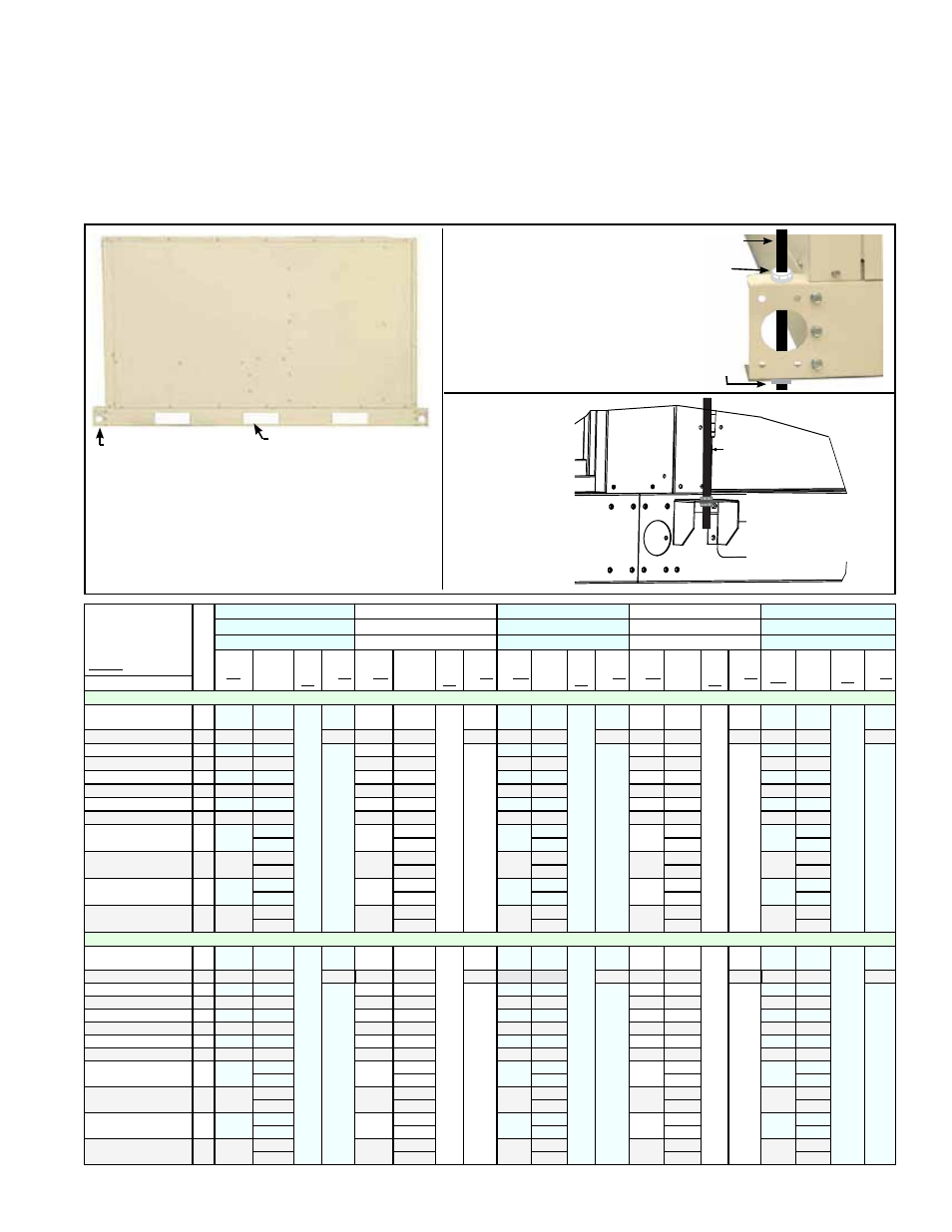
FIGURE 4 - Heavy
Gauge Base has Forklift
Holes and Lifting Holes
plus Holes for Attach-
ing 1/2” Threaded Rod
for Suspension
TABLE 7A -
Suspension Point
Dimensions - PDH,
SDH, PEH, and PXH
without hot water heat
Suspension Points
(qty)
PDH/SDH 75, 100
PDH/SDH 125, 150
PDH/SDH 175, 200, 225
PDH/SDH 250, 300
PDH/SDH 350, 400A
PEH 10A, 20A, 40A
PEH 15B, 30B, 60B
PEH N/A
PEH 30D, 60D, 90D, 120D
PEH 40E, 80E, 120E
PXH 000A (no heat only)
PXH 000B (no heat only)
PXH 000C (no heat only)
PXH 000D (no heat only)
PXH 000E (no heat only)
Corner to Corner
Hanger Point
Length
Discharge Corner
Hanger Point To
Intermediate
Side Hanger
Points
Corner to
Corner
Hanger
Point
Width
Intermediate
Side Hanger
Point Width
Corner to
Corner Hanger
Point Length
Discharge Corner
Hanger Point To
Intermediate
Side Hanger
Points
Corner to
Corner
Hanger
Point
Width
Intermediate
Side Hanger
Point Width
Corner to
Corner Hanger
Point Length
Discharge
Corner Hanger
Point To
Intermediate
Side Hanger
Points
Corner to
Corner
Hanger
Point
Width
Intermediate
Side Hanger
Point Width
Corner to
Corner Hanger
Point Length
Discharge
Corner Hanger
Point To
Intermediate
Side Hanger
Points
Corner to
Corner
Hanger
Point
Width
Intermediate
Side Hanger
Point Width
Corner to
Corner
Hanger Point
Length
Discharge
Corner Hanger
Point To
Intermediate
Side Hanger
Points
Corner to
Corner
Hanger Point
Width
Intermediate
Side Hanger
Point Width
Configuration
Dimensions (inches)
Blower/furnace (PDH/SDH/
PEH) or blower only (PXH)
4
56-5/8
N/A
32-5/8
N/A
56-5/8
N/A
42-5/8
N/A
72-5/16
N/A
32-5/8
N/A
72-5/16
N/A
48-7/8
N/A
72-5/16
N/A
56-7/8
N/A
with Evap Cooler (ECC)
4
87-11/16
N/A
N/A
87-11/16
N/A
N/A
103-5/8
N/A
N/A
103-5/8
N/A
N/A
103-5/8
N/A
N/A
with Mixing Box (MXB)
6
87-11/16
53-31/32
35-3/4
87-11/16
53-31/32
45-3/4
103-5/8 69-21/32
35-3/4
103-5/8 69-21/32
52
103-5/8 69-21/32
60
with Coil Cabinet (AU 5 or 6)
6
84-7/16
53-31/32
84-7/16
53-31/32
100-1/8 69-21/32
100-1/8 69-21/32
100-1/8 69-21/32
with Coil Cab (AU7)
6
109-1/2
53-31/32
109-1/2
53-31/32
125-3/16 69-21/32
125-3/16 69-21/32
125-3/16 69-21/32
with ECC & MXB
6
118-3/4
53-31/32
118-3/4
53-31/32
134-7/16 69-21/32
134-7/16 69-21/32
134-7/16 69-21/32
with ECC & AU5 or AU6
6
115-15/32 53-31/32
115-15/32 53-31/32
131-3/16 69-21/32
131-3/16 69-21/32
131-3/16 69-21/32
with ECC & AU7
6
140-7/8
53-31/32
140-7/8
53-31/32
156-1/4 69-21/32
156-1/4 69-21/32
156-1/4 69-21/32
with MXB & AU5 or AU6
8
115-15/32
53-31/32
115-15/32
53-31/32
131-3/16
69-21/32
131-3/16
69-21/32
131-3/16
69-21/32
81-25/32
81-25/32
97-1/2
97-1/2
97-1/2
with MXB & AU7
8
140-7/8
53-31/32
140-7/8
53-31/32
156-1/4
69-21/32
156-1/4
69-21/32
156-1/4
69-21/32
106-25/32
106-25/32
122-1/2
122-1/2
122-1/2
with ECC, MXB, & AU5
or AU6
8
146-1/2
53-31/32
146-1/2
53-31/32
162-1/4
69-21/32
162-1/4
69-21/32
162-1/4
69-21/32
81-25/32
81-25/32
97-1/2
97-1/2
97-1/2
with ECC, MXB, & AU7
8
171-9/16
53-31/32
171-9/16
53-31/32
187-5/16
69-21/32
187-5/16
69-21/32
187-5/16
69-21/32
106-25/32
106-25/32
122-1/2
122-1/2
122-1/2
Dimensions (mm)
Blower/furnace (PDH/SDH/
PEH) or blower only (PXH)
4
1438
N/A
829
N/A
1438
N/A
1083
N/A
1837
N/A
829
N/A
1837
N/A
1241
N/A
1837
N/A
1445
N/A
with Evap Cooler (ECC)
4
2227
N/A
N/A
2227
N/A
N/A
2632
N/A
N/A
2632
N/A
N/A
2632
N/A
N/A
with Mixing Box (MXB)
6
2227
1371
908
2227
1371
1162
2632
1769
908
2632
1769
1321
2632
1769
1524
with Coil Cabinet (AU 5 or 6)
6
2145
1371
2145
1371
2543
1769
2543
1769
2543
1769
with Coil Cab (AU7)
6
2781
1371
2781
1371
3180
1769
3180
1769
3180
1769
with ECC & MXB
6
3016
1371
3016
1371
3415
1769
3415
1769
3415
1769
with ECC & AU5 or AU6
6
2933
1371
2933
1371
3332
1769
3332
1769
3332
1769
with ECC & AU7
6
3578
1371
3578
1371
3969
1769
3969
1769
3969
1769
with MXB & AU5 or AU6
8
2933
1371
2933
1371
3332
1769
3332
1769
3332
1769
2077
2077
2477
2477
2477
with MXB & AU7
8
3578
1371
3578
1371
3969
1769
3969
1769
3969
1769
2712
2712
3112
3112
3112
with ECC, MXB, & AU5
or AU6
8
3721
1371
3721
1371
4121
1769
4121
1769
4121
1769
2077
2077
2477
2477
2477
with ECC, MXB, & AU7
8
4358
1371
4358
1371
4758
1769
4758
1769
4758
1769
2712
2712
3112
3112
3112
Whichever method is used, test lift the unit to be sure that it is secure. Then lift slowly fol-
lowing safe procedures. Lifting and suspension are the responsibility of the installer.
Depending on the type and number of optional modules, each unit has either four, six,
or eight point suspension. See
TABLE 7 A, B, or C and FIGURE 2, page 9. Extend
1/2” threaded hanger rod through both top and bottom of the base at each corner sus-
pension point. Secure with flat washers and locknuts (See
FIGURE 4, top right). When
six or eight point suspension is required, attach 1/2” threaded rod to each side hanger
bracket using a locknut and a flat washer on both the top and bottom of the hanger
bracket (See
FIGURE 4, bottom right).
• For rigging, use all four corner lifting holes
AND eyebolts placed in all side hangers of
units with side suspension points
• Use spreader bars so that lifting is with
vertical force only.
• Always test lift to be sure the unit is secure.
Forklift holes for moving
& lifting (on both sides
)
Lifting hole for rigging
(one at each corner)
1/2” Threaded
Rod
Attach with locknut
and flat washer on
top and on bottom
of each side hanger.
Suspend
from Corner
Hangers -
applies to all
units
Suspend from
Intermediate
Side Hangers
- applies to
all units with
a cooling coil
cabinet and/or
a mixing box
1/2” Threaded Rod
Locknut and flat
washer on top
Flat washer
and Locknut
on bottom
Non-Control Side of Basic Unit
(If configuration has more than
two optional modules, check
labels for recommended
lifting side using forklift.)