0 mechanical (cont’d) – Reznor SHH (Indoor PreevA) Unit Installation Manual User Manual
Page 20
Form I-PDH/SDH/PEH/SHH/PXH, Page 20
CAUTION: Apply general plumbing practices if pipe insulation
or heat tapes are required to prevent freezing of the condensate
drain system.
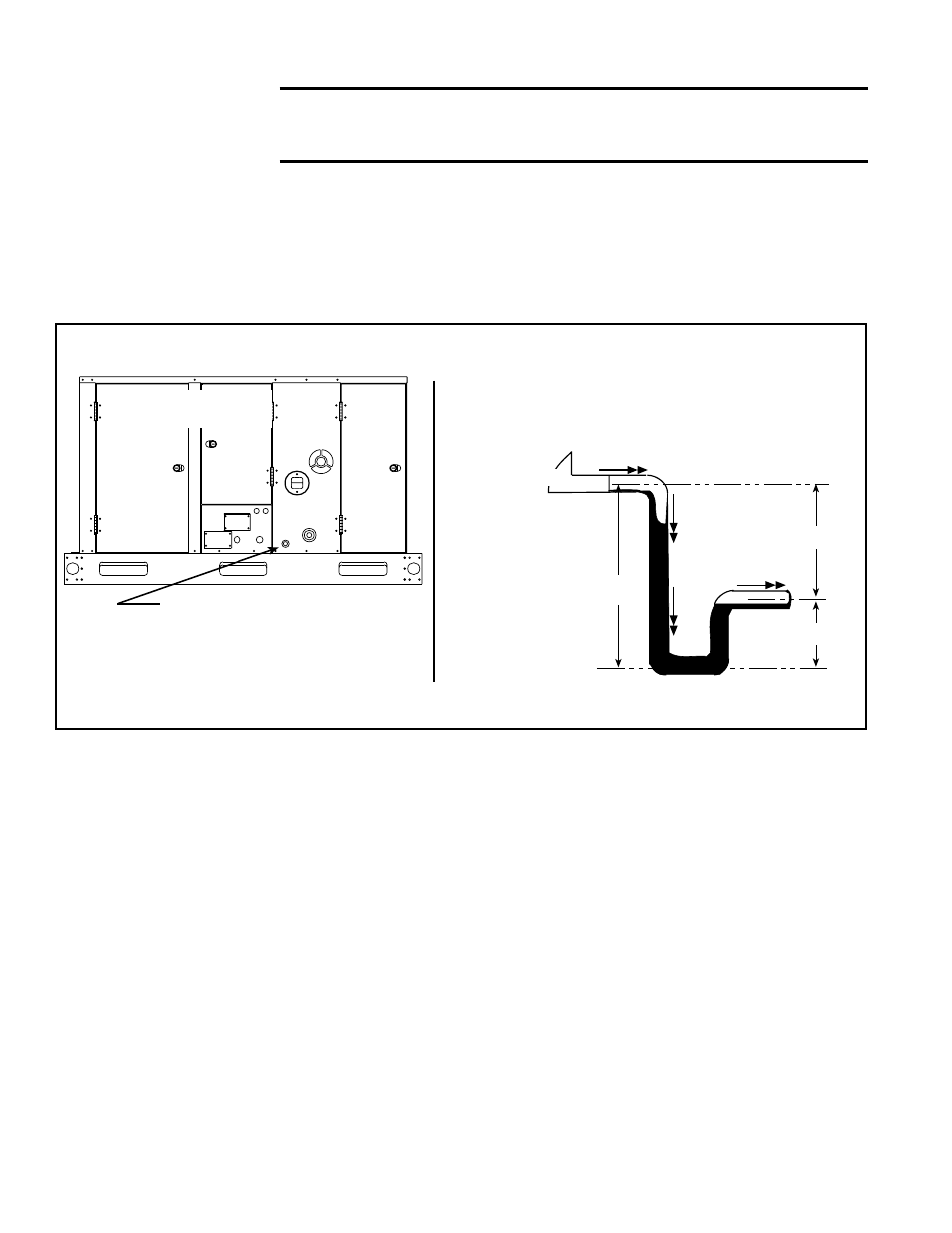
A Model SDH and PDH heat section with Option CS2 is equipped with a condensate
drain with a 1/2” NPT connection. See location in
FIGURE 11. Models PDH and SDH
require a heat section condensate drain when one or more of the three situations listed
below exists:
• A cooling coil is installed upstream of the heat section.
• The temperature rise for a makeup air unit is equal to or less than 60°F.
• The space temperature to be maintained by the indoor heating unit installed in
the space is 45°F or less.
6.2.1 Heat Section
Condensate Drain -
Models PDH and SDH
with Option CS2
FIGURE 11 - Location of the Burner Condensate Drain Connection and Trap Requirements on
Models SDH and PDH with Option CS2
1/2” NPT
connection for installer
to connect a condensate drain line.
Put a trap in the line as shown on the right
and empty it into a sanitary drain system.
6.2.2 Secondary Heat
Exchanger, Burner,
and Vent Condensate
Drains - Model SHH
During operation of the high-efficiency Model SHH unit, condensate is both produced
in the heater and collected from the venting system. Therefore, the installation requires
a condensate drain with a trap from both the secondary heat exchanger (
FIGURE 12)
and the vent pipe.
NOTE: Instructions for installing the drain in the vent pipe are in the
venting manual (Form I-SHH-V, P/N 257037).
In addition, if the system includes a cooling coil module, a third condensate line is
required at the burner condensate drain (
FIGURE 12). When installing the burner con-
densate drain, comply with the trap requirements in
FIGURE 11. If there is no cooling
coil module, cap the burner drain connection.
For safe performance of the heater, each condensate drain must include a trap and
each trap must be filled with water. Drains may be joined downstream of the traps. All
condensate drains must empty into a sanitary drain system.
Check codes to be certain that this is permitted. (Condensate from the heater has a PH
of 6. Actual PH may vary depending on fuel and combustion air constituents.) Model
SHH Sizes 130 and 180 will produce approximately one gallon (4 liters) of condensate
per hour. Sizes 260 and 350 will produce approximately two gallons (8 liters) of con-
densate per hour.
A condensate disposal system that relies on gravity should be satisfactory for most
suspended installations since these heaters are normally several feet above the floor.
If a gravity system is not possible with the installation, a condensate pump may be
installed. There are a number of commercially available pumps made for this purpose.
If using a condensate pump, follow the pump manufacturer’s installation recommenda-
tions.
Minimum Trap Dimensions for Burner Condensate
Drain -- Option CS2 on Models PDH and SDH
(and when used on Model SHH; see 6.2.2 below.)
PDH or SDH with
Option CS2
NOTE: If the system includes a cooling coil cabinet, the cooling coil cabinet also requires a condensate
drain. See Paragraph 6.6.3.
B
A
A/2
C
L
C
L
C
L
Unit
Water Flow
Water Flow
A = 3” (76mm)
minimum
B = A + A/2
6.0 Mechanical
(cont’d)
6.2 Gas Heat Section Condensate Drain(s) (cont’d)