0 controls and operation (cont’d) – Reznor SHH (Indoor PreevA) Unit Installation Manual User Manual
Page 52
Form I-PDH/SDH/PEH/SHH/PXH, Page 52
ential of 2-1/2°F. Due to different CFM settings and outside air temperatures, the aver-
age downstream outlet temperature may not match the ductstat setting exactly. After
the installation is complete, adjust the setpoint of the ductstat to achieve the desired
average outlet air temperature.
Optional Ductstat with Electronic Remote Setpoint Module (Options AG15 and
AG16) - The factory-installed sensing probe must be field-wired to a remote tempera-
ture selector. The temperature selector has an operating range to 120°F. Follow the
wiring diagram with the unit and the manufacturer’s instructions for wiring and installa-
tion.
CAUTION: Be sure heat/cool selector switch is set at “Heat” position. There will
be one module for selecting temperature and one-stage adder module. The optional
digital display module is only in Option AG16. See
FIGURE 44.
8.2.4 Constant
Discharge Air
Temperature with
Maintained Thermal
Efficiency - Makeup
Air Heating Only
Application (Options
AG60, AG61, & AG62)
- applies to Models
PDH and SDH
Two-Speed Venter System in Options AG60, AG61,
and AG62 - A proprietary electronically controlled venter
system provides the correct quantity of combustion air
to maintain an overall average of 81% thermal efficiency
through a range of gas inputs from 100 to 33 percent for
natural gas and through a gas input range of 100 to 40
percent for propane gas. The venter’s low speed opera-
tion is controlled by an electronic board (
FIGURE 45)
and a two-stage ductstat (either
FIGURE 43 or 44).
The proprietary electronically controlled venter system
always operates at high speed during pre-purge and
post-purge periods. Speed selection occurs after there
is a call for burner ignition.
Optional Unit-Mounted Ductstat with Capillary Tub-
ing (Option AG60) - Uses the unit-mounted control
illustrated in
FIGURE 43 with an adjustable range from
0° to 120°F. Due to different CFM settings and outside
air temperatures, the average downstream outlet tem-
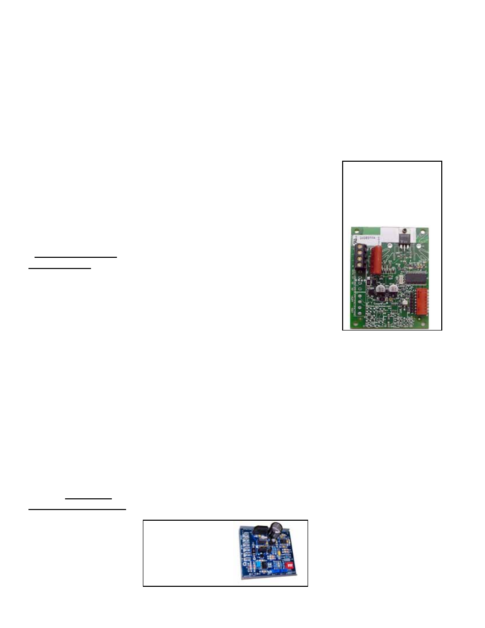
FIGURE 45 -
Venter
Speed Control Board in
Control Options AG8,
AG9, AG9H, AG40, AG60,
AG61, AG62, DG1, DG2,
DG5, DG6, D12B, D12C
perature will be constant but may not match the ductstat setting exactly. After the instal-
lation is complete, adjust the setpoint of the ductstat to achieve the desired outlet air
temperature.
Optional Ductstat with Electronic Remote Setpoint Module (Options AG61 and
AG62) - The factory-installed sensing probe must be field-wired to the 0-120°F remote
temperature selector illustrated in
FIGURE 44.
The remote modules are shipped separately for field installation. Follow the wiring
diagram with the unit and the manufacturer’s instructions for wiring and installation.
CAUTION: Be sure heat/cool selector switch is set at “Heat” position. There will be one
module for selecting temperature and one-stage adder module.
The optional digital display module is used only in Option AG62. See
FIGURE 44.
FIGURE 46 -
Maxitrol Signal
Conditioner, P/N
134170, used in
Options AG40,
DG2, and DG6
8.2.5 Modulation Gas
Control with Field-
Supplied Digital
Control (Option
AG40) - applies to
Models PDH and SDH
Optional Modulation Gas Control with Field-Supplied Controller (Option AG40) -
With this control, the modulation gas heating system is identical to digital Options DG2
and DG6 on page 53. The programmable digital controller is not supplied. The unit is
equipped with a Maxitrol signal conditioner (
FIGURE 46) that accepts an input signal of
either 4-20 milliamps or 0-10 volts from a field-supplied controller and converts it to the
0-20 volt DC current required to control the modulating valve. Temperature selection or
building management is controlled by customer-supplied software.
8.0 Controls and
Operation
(cont’d)
8.2 Analog Controls
for Heating or
Heating/Makeup
Air (cont’d)
8.2.3 Two-Stage Operation - Makeup Air Heating Only Application
(Option AG3, AG15, or AG16) (cont’d)