0 electrical supply and wiring (cont’d), 6 other optional electrical components (cont’d) – Reznor SHH (Indoor PreevA) Unit Installation Manual User Manual
Page 50
Form I-PDH/SDH/PEH/SHH/PXH, Page 50
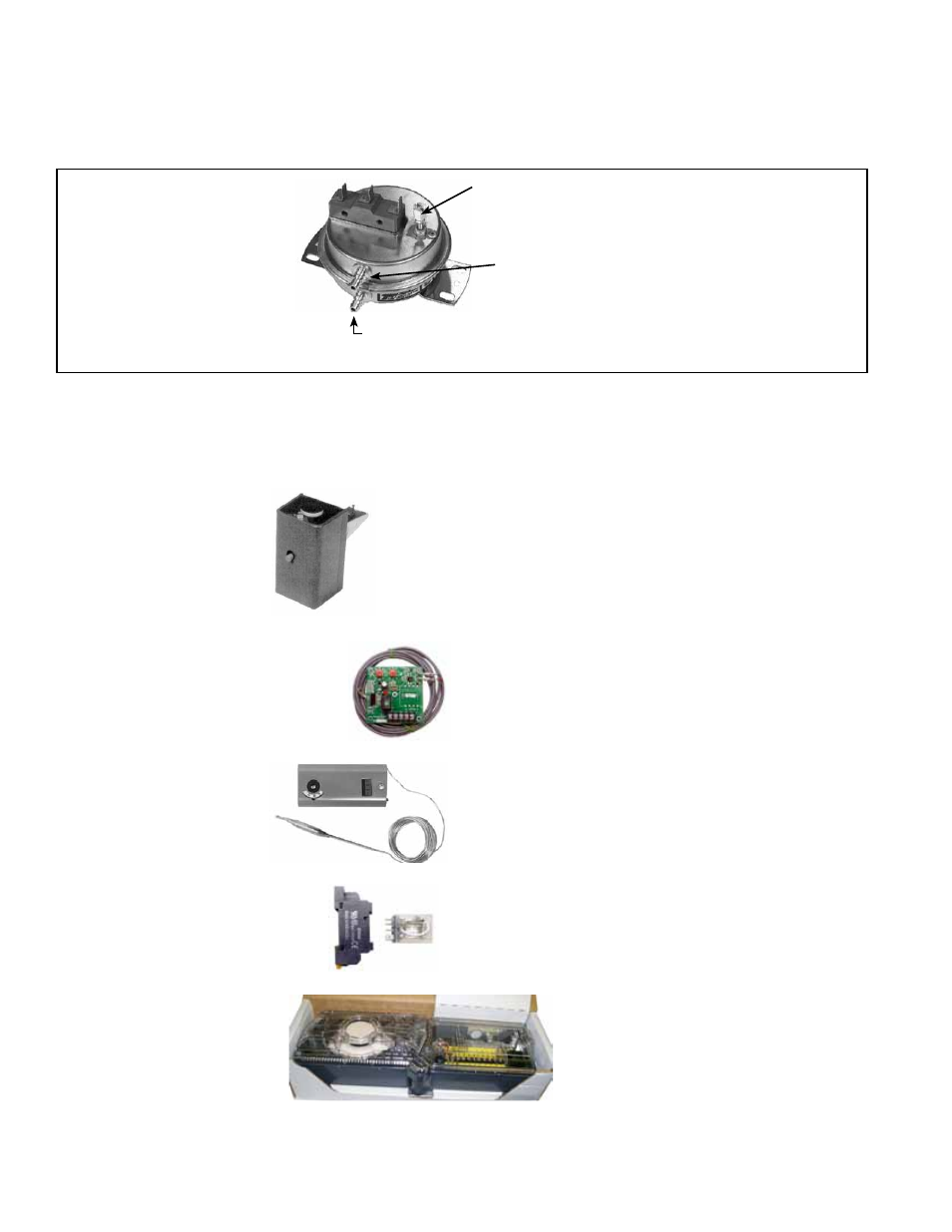
FIGURE 42 - Dirty
Filter Switch, P/N
105507 (must be set
prior to continuous
operation)
Set screw (on front of switch) must be
manually adjusted after the system is in
operation.
Positive pressure connection is toward the “back or
bottom” of the switch (senses air inlet side of filters)
Negative pressure connection is toward
the “front or top” of the switch (senses
blower side of filters)
7.6.3 Convenience
Outlet, Option BC2 -
PDH, SDH, PEH, SHH,
PXH
If the unit is equipped with a convenience outlet, it will have an externally accessible,
weatherproof 115 volt, duplex, ground fault outlet on the control side of the cabinet.
A
separate 115 volt power supply is required.
Option BD4 (factory-installed) or Option BD5 (field-installed) 200°F
firestat is
P/N 42782. Firestat Option BD4 is factory installed in the
mixing box to sense the temperature of the return air. Firestat Option
BD5 is shipped separately for field installation in the discharge duc-
twork.
The firestat will shutdown the unit if temperature setpoint is reached.
Comply with local building codes.
7.6.4 Firestat, Option
BD4 or BD5 - PDH,
SDH, PEH, SHH, PXH
the filter light is energized or the screw is bottomed out. At that point, adjust the set-
screw three full turns counter clockwise or until the screw is top ended. At that setpoint,
the filter light will be activated at approximately 50% filter blockage.
Limit control,
P/N 211480, is factory installed to monitor
the temperature of the discharge air. Setpoint of automatic
reset control is adjustable. (
NOTE: Not needed with digital
controls; standard function of the digital controller.)
7.6.5 Discharge Temperature
Low Limit (Freezestat), Option
BE2 - PDH, SDH, SHH, PEH,
PXH
7.6.6 High Ambient
Limit Control (burner
cutoff), Option BN2 -
PDH, SDH, SHH, PEH,
PXH
The high ambient limit control monitors the temperature
of the outside air and activates to shutoff the heat if the
setpoint is reached. The control has an adjustable setpoint
and resets automatically.
P/N is 126170.
A DPDT plug-in relay is installed for coordination of unit
operation with the operation of the building exhaust fan.
Plug-in relay
P/N is 211411; socket P/N is 211415.
7.6.7 Exhaust Fan Interlock
Relay, Option BG9 - PDH,
SDH, SHH, PXH, PEH
This photoelectric smoke detector is
shipped separately to be installed in the
discharge ductwork. Follow installation
instructions supplied with the control and
the wiring on the unit wiring diagram.
Comply with local building codes.
P/N of the device is 159553.
7.6.8 Smoke Detector,
Option SA1 - PDH,
SDH, PEH, SHH, PXH
7.0 Electrical
Supply and
Wiring (cont’d)
7.6 Other Optional Electrical Components (cont’d)
7.6.2 Remote Console for Controls (cont’d)