3 wiring diagram and unit wiring requirements, 4 control wiring, 1 control wiring requirements – Reznor SHH (Indoor PreevA) Unit Installation Manual User Manual
Page 45: 2 analog or digital controls
Form I-PDH/SDH/PEH/SHH/PXH, Page 45
WARNING - applies to Models PDH, SDH, and SHH:
If you turn off the power supply, turn off the gas.
Optional On/Off Switch, Option BA6 - The unit my be equipped with a cabinet-
mounted non-fusible, lockable, service on/off switch. The switch is conveniently located
on the control side of the unit.
Optional Phase Loss or Low/High Voltage Protection, Opt BF15 or BF14 - A
3-phase system may be equipped with an optional phase loss protection device.
Option BF15 is an auto-reset control that shuts down the unit on phase loss or phase
reversal. Option BF14 performs the same function but will also shut down the unit on
high or low voltage condition.
CAUTION: If any of the original wire as supplied with the appliance
must be replaced, it must be replaced with wiring material having a
temperature rating of at least 105°C, except for sensor lead wires which
must be 150°C. See Hazard Levels, page 2.
7.3 Wiring Diagram
and Unit Wiring
Requirements
Each unit has a custom wiring diagram in the control compartment. All optional elec-
trical components ordered with the unit are shown on the wiring diagram. Codes for
options ordered are listed across the bottom of the diagram. To identify option codes,
see list in the
APPENDIX on page 68.
Keep the wiring diagram and all manuals for future reference.
7.4 Control Wiring
The heater is equipped with a low voltage (24V) control circuit. A wiring diagram is in
the high voltage electrical compartment.
Control wiring connected to a thermostat, a switch, a discharge air sensor, a remote
temperature selector or sensor, an amplifier, or the valve must not be run close to or
inside conduit with power or ignition wires.
7.4.1 Control Wiring Requirements
Digital Control Signal Wiring Recommendations and Requirements
For optimum temperature control performance, the manufacturer recommends that the
analog and digital inputs (zone sensors, discharge air sensors, etc.) connected to the
main controller (used in heating/cooling control DG and D12 Options) be routed to the
unit in one of the following manners:
1) In separate conduits, isolated from 24 VAC controls and line voltage power to the
unit, OR
2) If the digital sensor wires are to be run in the same conduit as the 24 VAC control
wiring, the sensor wiring must be completed using shielded cable and bundled
separately from the 24 VAC control wiring. The shield must be drained at the unit
and taped on the opposite end.
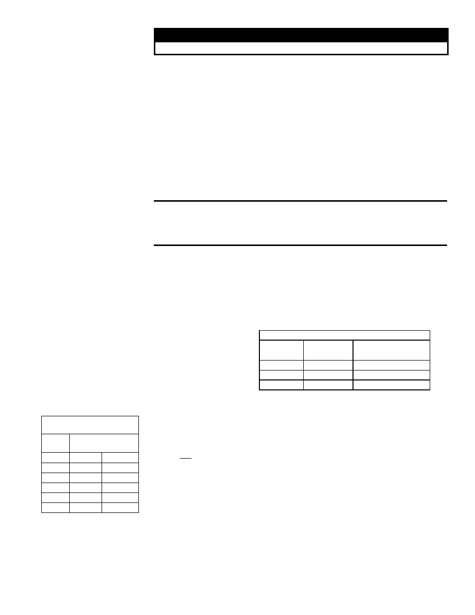
See
TABLE 30 for digital control sensor wire gauge and length requirements.
TABLE 30 - Digital
Control Sensor Wire
TABLE 29 - 24V Control
Wiring Gauge and
Length Requirements
7.4.2 Analog or Digital
Controls
Type of control varies with option selection (identified on the unit wiring diagram). Con-
trol may be analog or digital depending on the control option selected. Option AG3,
AG15, AG16, AG58, AG60, AG61, and AG62 controls are analog; Option DG1, DG2,
DG5, DG6, D12B, D12C, D12D, D12E, D12F, and D12G controls are digital. Option
AG40 is designed for digital control from a field-supplied source. Optional controls are
identified on the wiring diagram supplied with the heater.
24V Field Control Wiring Length/Gauge
Total Wire
Length
Distance from
Unit to Control
Minimum Recommended
Wire Gauge
150ft (46M)
75ft (23M)
18
250ft (76M)
125ft (38M)
16
350ft (107M)
175ft (53M)
14
Maximum Sensor Wire Length
for less than 1°F Signal Error
Wire
Gauge
Maximum Sensor Wire
Length (Digital Control)
AWG
Feet
Meters
14
800
244
16
500
152
18
310
94
20
200
61
22
124
38