Reznor SHH (Indoor PreevA) Unit Installation Manual User Manual
Page 37
Form I-PDH/SDH/PEH/SHH/PXH, Page 37
CAUTION: Joint where supply air duct attaches to the furnace must be sealed securely to
prevent air leakage. Leakage can cause poor combustion, shorten heat exchanger life, and
cause poor performance. See Hazard levels, page 2.
Requirements and
Recommendations
for Connecting and
Installing Discharge
Ductwork - All Models
• Type of Ductwork - The type of duct installation to be used depends in part on the
type of construction of the roof (whether wood joist, steelbar joist, steel truss, pre-
cast concrete) and the ceiling (whether hung, flush, etc.).
• Ductwork Material - Rectangular duct should be constructed of not lighter than
No. 26 U.S. gauge galvanized iron or No. 24 B & S gauge aluminum.
• Ductwork Structure - All duct sections 24 inches (610mm) or wider, and over 48
inches (1219mm) in length, should be cross broken on top and bottom and should
have standing seams or angle-iron braces. Joints should be S and drive strip, or
locked.
•
Through Masonry Walls - No warm air duct should come in contact with masonry
walls. Insulate around all air ducts through masonry walls with not less than 1/2”
(1” is recommended) of insulation.
• Through Unheated Space - Insulate all exposed warm air ducts passing through
an unheated space with at least 1/2” (1” is recommended) of insulation.
•
Duct Supports - Suspend all ducts securely from adjacent buildings members. Do
not support ducts from unit duct connections.
• Duct Sizing - Proper sizing of the supply air ductwork is necessary to ensure a
satisfactory heating installation. The recognized authority for such information is
the Air Conditioning Contractors Association (www.acca.org), 2800 Shirlington
Road, Suite 300, Arlington, VA 22206. A manual covering duct sizing in detail may
be purchased directly from them.
CAUTION: An external duct system static pressure not within the
limits shown on the rating plate, or improper motor pulley or belt
adjustment, may overload the motor. See Hazard Levels, page 2.
• Removable Panel (See FIGURE 31.) - The ductwork should have a removable
access panel. This opening must be accessible when the furnace is in service and
should be large enough to view smoke or reflected light, to detect the presence of
leaks in the heating equipment, and to check for hot spots on the heat exchanger
due to poor air distribution or lack of sufficient air (cfm). The cover for the opening
must be attached in such a manner as to prevent leakage.
• Horizontal Discharge Duct Length - A minimum horizontal duct run of 24”
(610mm) is recommended before turns or branches are made in the duct system
to reduce losses at the furnace outlet.
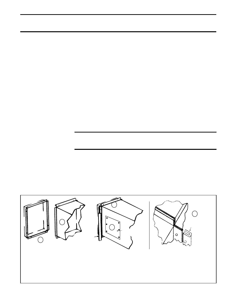
FIGURE 31 -
Connecting Discharge
Ductwork
(1) If the heater has an optional duct flange, the flanges turn out as shown. (2) Shape duct connection as shown
with “U” on top and bottom and “L” on sides.
(3) Provide for sealed access panel in the ductwork. This opening must
be accessible when the furnace is in service and should be large enough to view smoke or reflected light, to detect
the presence of leaks in the heating equipment, and to check for hot spots on the heat exchanger due to poor air
distribution or lack of sufficient air (cfm). The cover for the opening must be attached in such a manner as to prevent
leakage.
(4) Slide “U” channels over top and bottom flanges on the heater. (5) Form field-supplied “U” channels over
side connections to seal. Drill and lock with sheetmetal screws.
Heater
Duct
Access Panel
in Duct
1
2
3
4
U Channel
(see englared
view on the right)
Furnace
Duct
U Channel of
Light Gauge Metal
5