4 ignition system - models pdh, sdh, and shh – Reznor SHH (Indoor PreevA) Unit Installation Manual User Manual
Page 59
Form I-PDH/SDH/PEH/SHH/PXH, Page 59
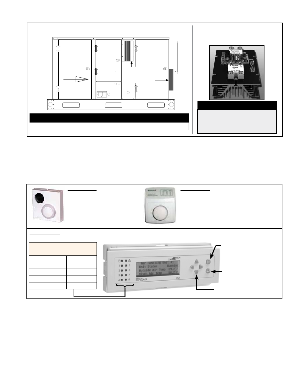
Side View - PEH
Airflow
SCR Control
and Heatsink
Locations
Blower
Electrical
Electric
Heat
Section
DANGER
High voltages are present
on the terminals of the
SCR power controller(s).
SCR Power Control and Heatsink
in Option D12D (one or two
required depending on amps)
FIGURE 50 - Locations of the SCR Power Controls with
Heatsinks on Model PEH w/ith Modulating Heat Control Option D12D
WARNING
The heatsink on the SCR power controllers is HOT to the touch.
Options D12B, D12C, D12D, D12E, and D12G include an outside air relative humidity
transmitter. Depending on whether the unit includes a mixing box, the sensor is either
factory-mounted in the mixing box or shipped separately for field installation in the inlet
duct. The sensor sequences compressor operation based on outdoor dewpoint. It is
recommended for humid and temperate climates.
Relative Humidity
Sensor
“ESC or Move Back”
Push for Menus
“OK” or “Enter”
Push to Select/Accept
“Scroll Buttons”
Display Lights
Symbol and 01 - 08
Unit ON/OFF
Alarm
Comp #1 ON
Reheat ON
Comp #1 ON
Not Used
Stg #1 Heat ON Not Used
Stg #1 Heat ON Not Used
Option CL67, P/N 260599,
Space Temperature Sensor,
has adjustable setpoint control
and unoccupied override.
Follow the instructions
included with the sensor and
the wiring diagram to install.
Option RB2A, P/N 223125, Remote User Interface, provides access to all of the same functions that are acces-
sible from the FX06 controller except Test Mode.
Option CL47, Room Dehumidistat, is
shipped separately for field installation. The
relative humidity inputs control reheat opera-
tion. Follow the instructions included with
the control and the wiring diagram to install.
NOTE: Applicable with reheat (Option AU7 or
AU8) only. Not available with Option D12F.
FIGURE 51 - Optional Space Mounted Accessories with Option D12 Digital Controls
8.3.3 Optional Space Mounted Accessories for D12 Control Options
8.4 Ignition System
- Models PDH,
SDH, and SHH
The gas-fired furnace is equipped with a direct spark integrated control module (circuit
board). The module monitors the safety devices and controls the operation of the ven-
ter motor and the gas valve between heat cycles. The module in Paragraph 8.4.1 is
used on all of the gas fired models. Depending on control option selected, Model SHH
uses either the control board in Paragraph 8.4.1 or 8.4.2.
8.4.1 Ignition Control
Module used in all
gas control options
EXCEPT Option AG58
and D12G
IMPORTANT: When using a multimeter to troubleshoot the 24 volt circuit of a unit with
this ignition controller, place the meter’s test leads into the 5 and 9 pin connectors
located on the ignition control. Do not remove connectors or terminals from the elec-
trical components. Doing so can result in misinterpreted readings due to the ignition
control board’s fault mode monitoring circuits.