Reznor SHH (Indoor PreevA) Unit Installation Manual User Manual
Page 41
Form I-PDH/SDH/PEH/SHH/PXH, Page 41
Hot Water Module
Discharge Options
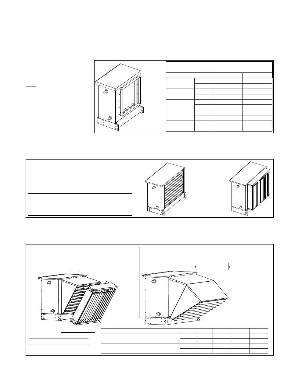
Depending on how it was ordered, the hot water module can have a standard opening
without duct flange for adding field-installed optional 30° or 60° discharge nozzle with
or without vertical louvers (Options CD2, CD3, CD4, or CD5). Or, the hot water module
discharge could have a factory-installed duct flange (Option AX4), horizontal louvers
(Option AX2), or horizontal and vertical louvers (Option AX3).
Outlet Duct Flange, Option AX4 - Optional duct flange is factory-installed. See dimen-
sions in
FIGURE 35B. See duct connection requirements in Paragraph 6.7.2.
FIGURE 35B - Option
AX4, Discharge Duct
Flange on Model PXH
with Optional Hot Water
Heat Module (Option
HW2)
TABLE 26B - Dimensions of Discharge Duct Flange on
Model PXH with an Optional Hot Water Heat Module
PXH with Option HW2
H
W
000A
inches
23-3/4
23-15/16
mm
603
608
000B
inches
23-3/4
33-15/16
mm
603
862
000C
inches
33-3/4
23-15/16
mm
857
608
000D
inches
33-3/4
39-15/16
mm
857
1014
000E
inches
33-3/4
47-15/16
mm
857
1218
Horizontal or Horizontal and Vertical Louvers, Options AX2 and AX3 - Factory-installed horizontal louvers (Option
AX2) are spring mounted in the discharge opening and do not have a frame. If there are factory-installed horizontal and
vertical louvers (Option AX3), the frame adds approximately 4” (102mm) to the length of the hot water module.
Adjust louvers for desired discharge airflow. (See
FIGURE 35C.)
Hot Water
Module,
Option HW2,
with factory-
installed
Duct Flange,
Option AX4
FIGURE 35C - Optional
Factory-Installed Horizontal or
Horizontal and Vertical Louvers
on a Hot Water Heat Module
Vertical Louver
frame extends
4” (102mm)
beyond the
cabinet.
Option AX2,
Horizontal
Louvers
Option AX3,
Horizontal
and Vertical
Louvers
CAUTION: To avoid getting burned, wear
gloves if adjusting louvers during heat
operation.
Optional
Hot Water
Module on
Model PXH
60-90° Nozzle
Option CD3
See TABLE 26B
below for length
added with
installation of a
nozzle option.
FIGURE 35D - Option CD2, 25-65° Nozzle
with Louvers and Option CD4, 25-65°
Nozzle with Horizontal and Vertical Louvers
on a Model PXH with a hot water module
Nozzle Option
CD2
CD3
CD4
CD5
PXH 000A or 000B with Hot Water Heat
Module (Option HW2)
inches
9
15-11/16
12-1/2
17-3/4
mm
229
398
318
481
PXH 000C, 000D, & 000E with Hot Water
Heat Module (Option HW2)
inches 13-9/16
23-5/8
17-1/8
25-11/16
mm
345
600
435
652
FIGURE 35E - Option CD3, 60-90° Nozzle has Two
Nozzle Sections.
Downturn Nozzles, Options CD2, CD3, CD4, and CD5 - Downturn nozzle options are shipped separately for field
installation. See the illustrations in
FIGURES 35D and 35E and follow the instructions shipped with the option pack-
age.
NOTE: The downturn nozzles in FIGURE 35D apply to a PXH with a hot water module. For all other models, see
FIGURE 34 on page 40.
TABLE 26B - Approximate
length added to the Hot
Water Module Discharge
If Option CD5
was ordered,
package
will have
CD3 nozzle
plus vertical
louvers as
shown in
FIGURE 35D.