0 controls and operation (cont’d) – Reznor SHH (Indoor PreevA) Unit Installation Manual User Manual
Page 60
Form I-PDH/SDH/PEH/SHH/PXH, Page 60
1) Call for Heat - The heating/cooling system controller calls for heat. The ignition sys-
tem circuit board checks to see that the limit switch is closed and the pressure switch is
open. If the limit switch is open, the circuit board responds as defined in the “Abnormal
Heat Cycle, Limit Switch Operation”. If the pressure switch is closed, the circuit board
will do four flashes on the green LED and wait indefinitely for the pressure switch to
open. If the pressure switch is open, the circuit board proceeds to prepurge.
2) Prepurge - The circuit board energizes the venter motor and waits for the pressure
switch to close. If the pressure switch does not close within 30 seconds of the venter
motor energizing, the circuit board will do two flashes on the green LED. The circuit
board will leave the venter motor energized indefinitely as long as the call for heat
remains and the pressure switch is open.
When the pressure switch is proven closed, the circuit board begins the prepurge time.
If flame is present any time while in prepurge, the prepurge time is restarted. If flame is
present long enough to cause lockout, the circuit board responds as defined in “Fault
Modes, Undesired Flame”.
The ignition system circuit board runs the venter motor for a 20 second prepurge time,
then proceeds to the ignition trial period.
3) Ignition Trial Period - The ignition system circuit board energizes the spark and
main gas valve. The venter remains energized. If flame is sensed during the first 16
seconds, the spark is de-energized. If flame has not been sensed during the first 16
seconds, the control de-energizes the spark output and keeps the gas valve energized
for an additional one second flame proving period. If flame is not present after the
flame proving period, the control de-energizes the gas valve and proceeds with ignition
re-tries as specified in “Abnormal Heat Cycle, Ignition Retry”. If flame is present, the
circuit board proceeds to steady heat.
4) Steady Heat - Circuit board inputs are continuously monitored to ensure limit and
pressure switches are closed, flame is established (sensor on both burner sections),
and the system controller call for heat remains. When the call for heat is removed, the
ignition system circuit board de-energizes the gas valve and begins postpurge timing.
5) Post Purge - The venter motor output remains on for a 45 second postpurge period
after the system controller is satisfied.
Normal Heat Cycle Operating Sequence with Controller in FIGURE 52.
NOTE: Abnormal Heat
Cycle Functions and
Ignition System Fault
Models for this ignition
controller are explained
in the Operation/
Maintenance/Service
Manual, Form O-PREEVA
& SHH
8.4.2 Ignition Control
Module used in Deep
Modulation Control
Options AG58 and
D12G - Model SHH only
Integrated Control Module for Gas Control Options AG58 and D12G -
The con-
trol module is located in the control compartment with an additional board to
control spark that is attached to the removable shield on the end of the burner.
8.4 Ignition System
- Models PDH,
SDH, and SHH
(cont’d)
8.0 Controls and Operation (cont’d)
Control Status - Green LED Codes
Steady ON ... Normal Operation, No call for heat
Fast Flash .... Normal Operation, Call for heat
1 Flash ......... System Lockout, Failed to detect or sustain
flame
2 Flashes ..... Pressure switch did not close within 30
seconds of venter motor
3 Flashes ..... High limit switch open
4 Flashes ..... Pressure switch is closed before venter
motor is energized
Steady OFF . Blown Fuse, No Power, or Defective Board
Flame Status - Yellow LED Codes
Steady ON ... Flame is sensed
Slow Flash ... Weak flame (current below 1.0 microamps
±50%)
Fast Flash .... Undesired Flame (valve open and no call
for heat)
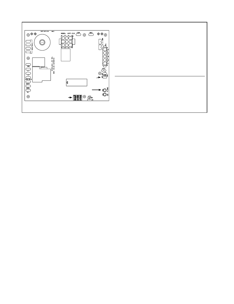
FIGURE 52 – Ignition Control Module (circuit board)
Spark
Transformer
Control
Plug
Fuse
Thermostat
Connections
Status
Lights
x
LED Lights
See NOTE
below.
NOTE: Set “blower off” dip switch setting to 45 seconds for makeup air application. Refer to the table
on the module for the appropriate settings.
Dip Switch Table