0 commissioning and startup (cont’d), 3 startup checklist and warnings (cont’d) – Reznor SHH (Indoor PreevA) Unit Installation Manual User Manual
Page 66
Form I-PDH/SDH/PEH/SHH/PXH, Page 66
on exhaust fans, such as range hoods and bathroom exhausts, so they shall
operate at maximum speed. Do not operate a summer exhaust fan. Close
fireplace dampers.
4. Light the heater following the lighting instructions. Adjust the control for
continued operation. Verify that combustion products are venting properly. After
determining that the heater vents properly, return doors, windows, exhaust
fans, and fireplace dampers to their previous conditions. If improper venting is
observed, the venting system must be corrected.
Models PDH, SDH, and SHH - With the unit in operation, measure valve outlet
gas pressure. If operated at high altitude, adjust outlet gas pressure for altitude if
required. See information and instructions in Paragraph 6.1.2 and 6.1.3.
Models PDH, SDH, and SHH - Turn the unit off and on, pausing two minutes
between each cycle. Observe for smooth ignition. On two-stage or modulating
burner systems, manipulate temperature adjustment slowly up and down to see if
control is sequencing or modulating properly.
If the system is equipped with an optional dirty filter switch, set the switch. Follow
the instructions in Paragraph 7.6.2.
If the system is equipped with a reheat pump, follow the instructions below to
check the refrigerant subcooling and superheat.
REMINDER: Keep all product literature. Place "Literature Bag" containing
Limited Warranty, this booklet, the venting manual, and any optional information
including the digital control instructions in an accessible location near the heater.
Follow the instructions on the envelope.
IMPORTANT: After at least 8 hours but no longer than a week of operation,
recheck the blower wheel, all set screws, blower pulley, motor pulley, and belt
tension. Make any required adjustments. (See Paragraph 6.8.)
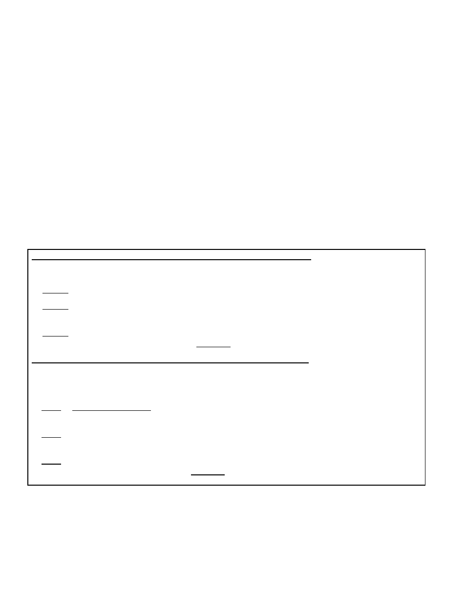
Instructions for Checking and Adjusting the Subcooling of an Isolated Circuit
Acceptable subcooling readings range from 14° to 18°F (7.8° to 10°C).
Measure and record temperature and pressure of the liquid line at the condenser coil outlet.
STEP 1) Record Measurements: Temperature = ________°F (°C) and Pressure = ________ psig
STEP 2) From Temperature/Pressure Conversion Chart, APPENDIX, page 69, convert Measured
Pressure (STEP 1) to ________°F (°C)
STEP 3) Subtract Measured Temperature (STEP 1) from Temperature from Conversion Chart (STEP 2)
________°F (°C) - ________°F (°C) = ________°F (°C) degrees of Subcooling
Instructions for Checking and Adjusting the Superheat of an Isolated Circuit
Superheat should be in the 8° to 12°F (4.5° to 6.7°C) range.
Measure and record temperature (insulate probe from surrounding air temperature) and pressure in the suction
line at the compressor inlet.
STEP 1) Record Measurements: Temperature =
_______°F (°C) and Pressure = _______ psig
STEP 2) From Temperature/Pressure Conversion Chart, APPENDIX, page 69, convert Measured Pres-
sure (STEP 1) to ________°F (°C)
STEP 3) Subtract Measured Temperature (STEP 1) from Temperature from Conversion Table (STEP 2)
_______°F (°C) - ________°F (°C) = ________°F (°C) degrees of Superheat
9.3 Startup Checklist and Warnings (cont’d)
9.0 Commissioning
and Startup
(cont’d)