0 mechanical (cont’d), 4 unit inlet air (supply air) (cont’d), Figure 18 - mixing box dimensions (table 16) – Reznor SHH (Indoor PreevA) Unit Installation Manual User Manual
Page 24: 2 mixing box dimensions
Form I-PDH/SDH/PEH/SHH/PXH, Page 24
6.4.4 Optional Mixing
Box (factory installed)
- Models PDH, SDH,
PEH, SHH, PXH
If the installation includes an Option MXB1 mixing box, it is factory installed in one of
the configurations illustrated in
FIGURE 17. The configuration and damper control (GE
Option, Paragraph 6.4.4.3) was determined when the unit was ordered.
GD1
GD2
GD3
GD4
GD5
Side Views - Arrows represent inlet airflow.
One Rear
Inlet
One Bottom
Inlet
One
Top Inlet
Two Inlets
(Bottom & Rear)
Two Inlets (Top
& Rear)
FIGURE 17 -
Option MXB1
Mixing Box
Configurations
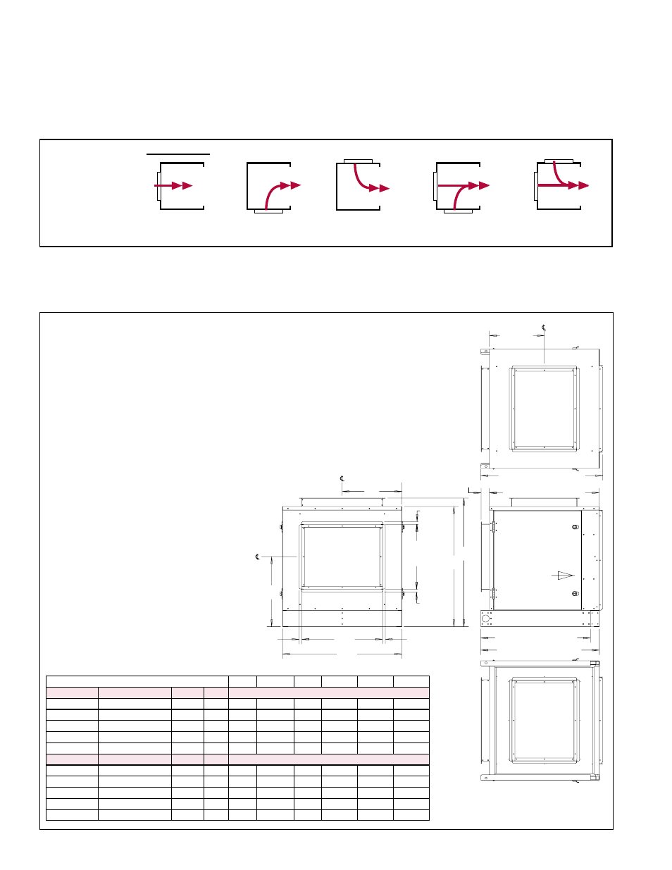
6.4.4.1 Mixing Box Configurations
All mixing box inlet air openings have a duct flange. (See dimensions in
FIGURE 18
and TABLE 16.) All inlet air ducts should be attached and sealed. A return air duct
must have a free area equal to the return duct connection.
Top
Inlet Air
Opening
15-9/16
(395mm)
34-17/32 (877mm)
31-1/16 (789mm)
2-11/32
(60mm)
Hinged
Access
Panels
(Both Sides)
Airflow
into attached
blower cabinet
31-1/16 (789mm)
35-9/16 (903mm)
Bottom
Inlet Air
Opening
E
F
A
D
B
C
3/4 (19mm)
3/4
(19mm)
18-3/8
(467mm)
3/4
(19mm)
3/4
(19mm)
Rear
Inlet Air
Opening
*
**
*
of opening
of opening
of opening
FIGURE 18 - Mixing Box Dimensions (TABLE 16)
Duct flange connections are the same size for all mixing box configurations -
D x 18-3/8” (467mm) opening with 3/4” (19mm) flanges.
Top and bottom openings are symmetrical.
* Centerline of opening is at 1/2 of 18-3/8”
= 9-3/16” (1/2 of 467mm = 233.5)
** Centerline of opening is at 1/2 of
D. Dimension E applies to location of
opening for all configurations.
TABLE 16 - Option MXB1
Mixing Box Dimensions
in FIGURE 18
Model and Size
A
B
C
D
E**
F*
PDH/SDH
PEH
SHH
PXH
Dimensions (inches)
75/100
10A/20A/40A
N/A
000A 33-3/4 36-13/32
34
22-7/8 16-59/64 19-25/32
125/150
15B/30B/60B
N/A
000B 43-3/4 36-13/32
34
26-1/2 21-59/64 19-25/32
175/200/ 225
N/A
130/180 000C 33-3/4 45-21-32 43-1/4 22-7/8 16-59/64 24-13/32
250/300
30D/60D/90D/120D
260
000D
50
45-21-32 43-1/4 34-3/4
25-3/64 24-13/32
350/400A
40E/80E/120E
350
000E
58
45-21-32 43-1/4 45-13/16 29-3/64 24-13/32
PDH/SDH
PEH
SHH
PXH
Dimensions (mm)
75/100
10A/20A/40A
N/A
000A
857
925
864
581
430
502
125/150
15B/30B/60B
N/A
000B 1111
925
864
673
557
502
175/200/ 225
N/A
130/180 000C
857
1160
1099
581
430
620
250/300
30D/60D/90D/120D
260
000D 1270
1160
1099
883
636
620
350/400A
40E/80E/120E
350
000E 1473
1160
1099
1164
738
620
6.4.4.2 Mixing Box
Dimensions
6.0 Mechanical
(cont’d)
6.4 Unit Inlet Air (Supply Air) (cont’d)