6 other optional electrical components – Reznor SHH (Indoor PreevA) Unit Installation Manual User Manual
Page 49
Form I-PDH/SDH/PEH/SHH/PXH, Page 49
The electric heat section has either heating only analog controls (Option EG1 or EG2)
or digital heating/cooing controls (Option D12E or D12D). With Option EG1, operation
of the heating elements is controlled by a single stage thermostat. With Option EG2,
the heat section provides two-stages of heat in response to a two-stage thermostat.
Digital control is either two stage (Option D12E) or modulating (Option D12D). See
Paragraph 8.3.2 and the control instruction form (CP-PREEVA-D12) for control infor-
mation.
7.6 Other Optional
Electrical
Components
Optional electrical components ordered with the unit are on the wiring diagram. For a
list of wiring diagram option codes and descriptions, see
APPENDIX, page 68.
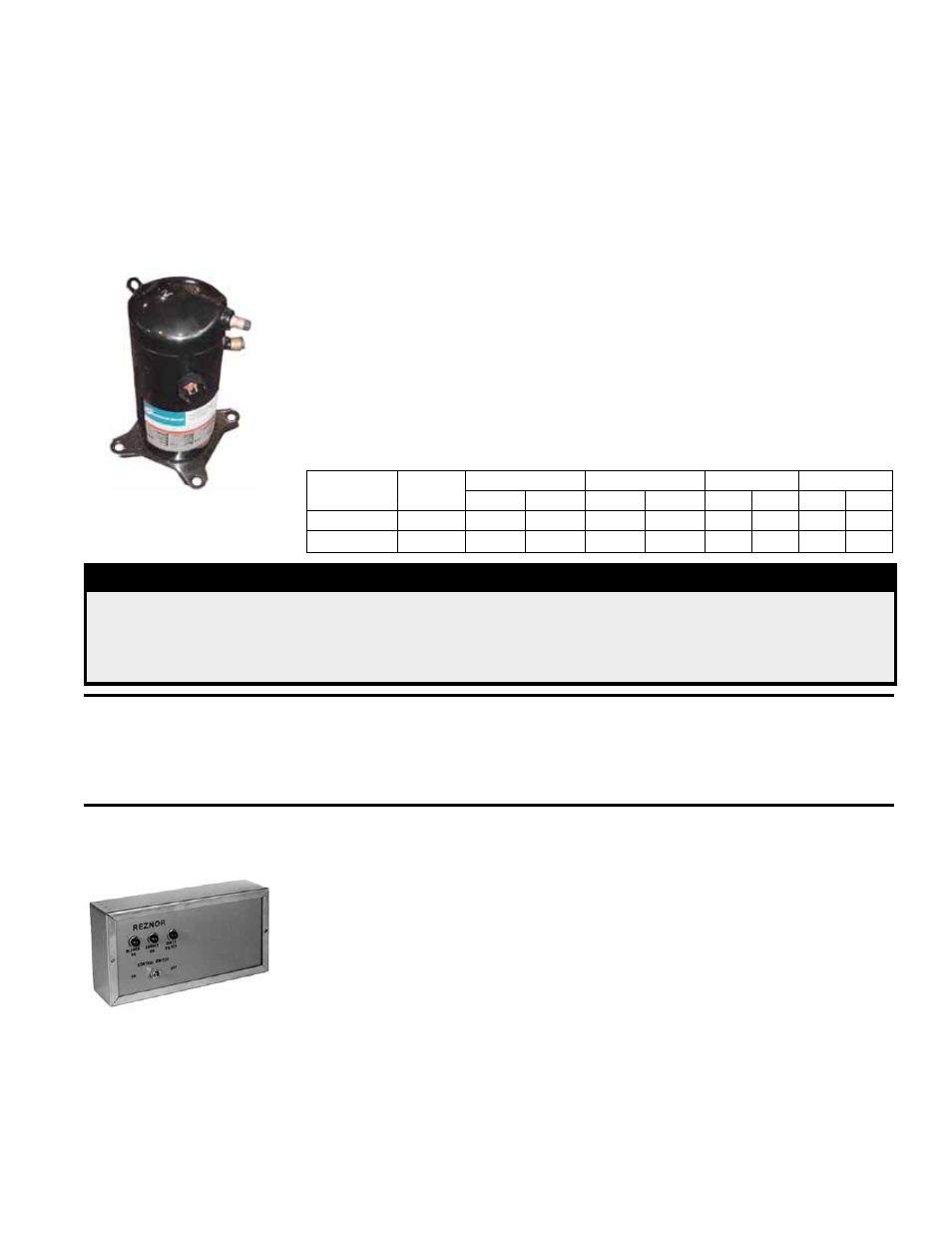
7.6.1 Reheat Module (Option AU7L or AU7R) Compressor - Models
PDH, SDH, SHH, PEH, PXH
The compressor in the optional reheat module is a high efficiency hermetic scroll type
that is factory charged with R410A refrigerant. The compressor has a low pressure
cutoff (LPCO) switch for protection against damage due to a loss of charge. This pro-
tection prevents short cycling on the internal overload (IOL) which can pump the oil
out of the compressor. The compressor also has a manual reset high pressure cutout
(HPCO).
NOTE: See Operation/Maintenance Form O-PREEVA (in the Literature Bag), for addi-
tional information on compressor maintenance and R410A refrigerant.
Compressor
Model
ARI
Tonnage
208/240 V 1 PH
208/240 V 3 PH
460 V3 PH
575 V3 PH
RLA
LRA
RLA
LRA
RLA
LRA RLA
LRA
ZP29K5
2.4
14.1
77.0
9.0
71.0
5.6
38.0
3.8
36.5
ZP57K3
4.8
30.1
158.0
20.5
155.0
9.6
75.0
7.6
54.0
Compressor - Reheat
circuit is charged with
R410A Refrigerant.
TABLE 33 - Reheat Module Compressor
DANGER
The reheat circuit contains R410A high pressure refrigerant. Hazards exist that could result
in personal injury or death. Installation, maintenance, and service should only be performed
by an HVAC technician qualified in R410A refrigerant and using proper tools and equip-
ment. DO NOT USE service equipment or tools designed for R22 refrigerant.
IMPORTANT: Do not release refrigerant to the atmosphere! If required service
procedures include the adding or removing of refrigerant, the service technician
must comply with all federal, state and local laws. The procedures discussed in
this manual should only be performed by a qualified HVAC technician.
7.6.2 Remote Console
for Controls
If the system includes an optional control console, it is shipped separately for field
installation. A selection of remote consoles is available with a variety of combinations
of factory-mounted controls. All consoles include burner and blower indicator lights
and may include a dirty filter indicator light (see below); a cooling on indicator light;
an on/off switch; a summer/winter/off control switch; a heat/vent/cool system switch;
and/or a potentiometer for damper control. The thermostat or room command module
may also be mounted on the console. Depending on the console selected, it may be
10-3/4” (273mm) or 15-3/4” (400mm) in length. All consoles are 7-5/8” (194mm) high
and 2-5/8” (67mm) deep. Consoles may be flush or recess mounted. If recessing (not
using the mount ring) subtract 7/8” (22mm) from the height and width.
Wire the 24V controls on the remote console according to the wiring diagram. Refer to
TABLE 29 on page 45 for minimum control wire gauge by length.
Dirty Filter Switch - If there is a dirty filter indicator light on the console, there is a dirty
filter switch in the electrical compartment. After the unit is started, before continuous
operation, the dirty filter switch must be set.
Instructions for Setting Dirty Filter Switch (See FIGURE 42.) - With clean filters
in place; all doors closed (except electrical compartment); and the blower opening,
increase the pressure setting by adjusting the setscrew on the switch clockwise until