7 unit discharge, 0 mechanical (cont’d), 4 ultra-violet light, option uv2 – Reznor SHH (Indoor PreevA) Unit Installation Manual User Manual
Page 36: Condensate drain use
Form I-PDH/SDH/PEH/SHH/PXH, Page 36
Seasonal Usage - At the beginning of the cooling season, inspect and clean the entire
cooling coil cabinet including the condensate drain pan. Thoroughly clean dirt, algae,
grease, and other contaminants. Inspect condensate drain pans, traps, and piping; fill
traps with water to ensure proper operation.
Year Round Usage - Climates or applications with cooling requirements year round
require more frequent inspections of the cooling coil cabinet and condensate drains.
Condensate Drain Use
If the cooling module was ordered with an optional ultra-violet light, the fixture is factory
installed but the bulb and other components are shipped in the blower compartment for
field installation. Follow the instructions on the option installation form shipped in the
parts bag. Option UV2 ultra-violet light requires its own power supply and disconnect
switch.
6.6.4 Ultra-Violet
Light, Option UV2
CAUTION: Do not touch bulb glass without gloves. Oil from fingerprints
will permanently etch bulb and weaken structure. Clean bulb after
handling.
WARNING
Do not use UVC lights for service lighting. Never expose eyes or
skin to ultra-violet light from any source.
6.7 Unit Discharge
Model PEH units require attachment of an outlet duct. They are equipped with a fac-
tory-attached discharge duct flange as shown in
FIGURE 30.
Model SDH, PDH, PXH, and SHH units may have ductwork or may discharge directly
into the space. Depending on which option was ordered, the discharge opening is
equipped with either an attached duct flange, factory-installed horizontal louvers, fac-
tory-attached horizontal and vertical louvers, or is an opening designed for field instal-
lation of an optional nozzle (Paragraph 6.7.4). If an outlet option is not selected, see
dimensions in
FIGURE 2, page 9.
Factory-installed horizontal louvers (Option AX2) are spring mounted in the discharge
opening and do not have a frame. If there are factory-installed horizontal and vertical
louvers (Option AX3), the frame adds approximately 4” (102mm) to the length of the
cabinet. Adjust louvers for desired discharge airflow.
6.7.1 Louvers, Option
AX2 or AX3 - PDH,
SDH, SHH
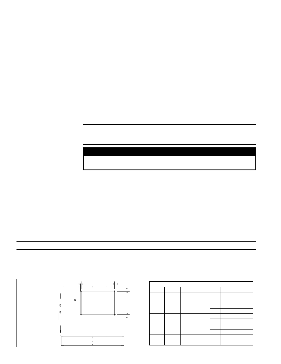
6.7.2 Discharge Duct Flange (factory installed
)
, Std on PEH; Option AX4 on PDH, SDH, SHH,
or PXH (without hot water heat)
X
Y
3/4(19mm)
3/4(19mm)
3/4
(19mm)
3/4
(19mm)
Discharge Opening
with Duct Flange
Std - PEH;
Opt AX4 - PDH,
SDH, SHH, PXH (no heat)
TABLE 22 - Dimensions of Discharge Duct Flange
PDH/SDH
PEH
SHH PXH (no heat)
X
Y
75, 100
10A, 20A,
40A
N/A
000A
inches
17-9/16
13-9/16
mm
446
345
125, 150
15B, 30B,
60B
N/A
000B
inches
27-9/16
13-9/16
mm
700
345
175, 200,
225
N/A
130,
180
000C
inches
20-3/4
22-13/16
mm
527
580
250, 300
30D, 60D,
90D, 120D 260
000D
inches
28-5/8
22-13/16
mm
727
580
350, 400A 40E, 80E,
120E
350
000E
inches
38-5/16
22-13/16
mm
973
580
FIGURE 30 -
Dimensions
of Discharge
Duct Flange
(factory
installed)
Dimensions for attaching ductwork are shown in
TABLE 22. The discharge duct flange is 4” (102mm) long with a 3/4”
(19mm) wide flange on all sides. See requirements and recommendations below for sizing and attaching ductwork.
6.0 Mechanical
(cont’d)
6.6 Cooling Module
- Option AU on
PDH, SDH, PEH,
SHH, and PXH
(cont’d)
The combination of airborne particles and moisture in the air handler can result in
algae formation in the drain pan and traps. The traps must be cleaned regularly to
avoid blockage that can slow or stop water flow, resulting in backup into the system.
If the drains have a cleanout opening (
FIGURE 29B), be sure to close the opening
after cleaning.
Drain Trap (cont’d)
CAUTION: To avoid getting burned, wear gloves if adjusting louvers during heat operation.