Dehumidification – Reznor SHH (Indoor PreevA) Unit Installation Manual User Manual
Page 53
Form I-PDH/SDH/PEH/SHH/PXH, Page 53
8.3.1 Optional Digital Heating/Cooling/Makeup Air Controls,
Options DG1, DG2, DG5, DG6 - PDH and SDH; PXH
8.3 Digital Controls
for Heating/
Cooling,
Makeup Air and
Dehumidification
Application NOTES: Options DG 1, 2, 5, and 6 do not apply to units with reheat pump
(dehumidification) Option AU7L or AU7R. Models SDH, PDH, and PXH with Option
AU7 require D12B or D12C; see Paragraph 8.3.2. Options DG 1, 2, 5, and 6 do not
apply to Model PEH or Model SHH; Model PXH is not a heating unit.
Digital control systems (Options DG1, DG2, DG5, and DG6) have a unit-mounted,
factory-wired, 24 volt, DDC programmable controller (
FIGURE 47); a venter speed
control board (
FIGURE 45); and a room command module (either FIGURE 48A or
48B). Options DG2 and DG6 with modulating gas heat have a Maxitrol conditioner
(
FIGURE 46).
The four DG control sequences include a wall-mounted Fan/Heat/Cool/Auto Switch.
Option DG1 - Room control with 2-stage gas heating and 3-stage cooling control. The wall mount interface allows
the user to adjust the space setpoint from 45°F to 95°F and select the unit mode. Unit modes are Cool Only, Heat
Only, Fan Only, Auto Mode, and Off.
Option DG2 - Room control with 4:1 modulated gas heat and 3-stage cooling control. The wall mount interface
allows the user to adjust the space setpoint from 45°F to 95°F and select the unit mode. Unit modes are Cool Only,
Heat Only, Fan Only, Auto Mode, and Off.
Option DG5 - Room control with 2-stage gas heating and 3-stage cooling control. The wall mount interface allows
the user to adjust the discharge air temperature ± 6°F from the factory-mounted controller setpoint and select unit
mode. Unit modes are Cool Only, Heat Only, Fan Only, Auto Mode, and Off.
Option DG6 - Room control with 4:1 modulated gas heat and 3-stage cooling control. The wall mount interface
allows the user to adjust the discharge air temperature ± 6°F from the factory-mounted controller setpoint and
select unit mode. Unit modes are Cool Only, Heat Only, Fan Only, Auto Mode, and Off.
The heating and cooling equipment will cycle to maintain the active heating discharge
or space temperature setpoint, based upon the unit mode and time of day schedule.
Unit Control Points - DG1, DG2, DG5, DG6
Analog Inputs
Digital Inputs
1) Space Temperature/Discharge Air Temperature
1) Dirty Filter
2) Space Temperature Setpoint (45-90°F) or (± 6°F Warmer/
Cooler)
2) Temporarily Unoccupied
Override
3) Outdoor Air Temperature
3) Occupied/Unoccupied
4) Mode Slider - Heat, Cool, Auto, Fan, Off
4) Air Proving/Phase Loss
5) Boost Mode
Digital Outputs
Analog Outputs
1) Fan
1) Modulating Gas Valve
2) Heat Stage 1
3) Heat Stage 2
4) Cool Stage 1
5) Cool Stage 2
6) Cool Stage 3
FIGURE 47 -
Programmable Digital
Controller, Johnson
Controls FX05 used in
all DG Options
Reference:
For
explanation on the settings
and functions of the FX05
programmable control, see
the instruction form in the
Literature Bag (Form CP-
PREEVA-DG with FX05).
Electronic Modulation between 50% and 100% Firing Rate (Options AG8, AG9 & AG9H)
Depending on the heat requirements as established by the thermistor sensor, the burner
modulates between 100% and 50% firing. The thermistor is a resistor that is temperature
sensitive in that as the surrounding temperature changes, the Ohms resistance changes
through the thermistor. This change is monitored by the solid state control center (ampli-
fier) which furnishes varying DC current to the modulating valve to adjust the gas input.
Each modulating valve is basically a regulator with electrical means of raising and lower-
ing the discharge pressure. When no DC current is fed to this device, it functions as a gas
pressure regulator, supplying 3.5" w.c. pressure to the main operating valve.
Refer to the wiring diagram supplied with the furnace for proper wiring connections.
Electronic modulation control systems for makeup air applications controlled by a field-
installed duct sensor (See Paragraph 6.7.3) and temperature selector (55-90°F) are
identified as either Option AG8 or Option AG9 & AG9H. The temperature selector set-
ting for Option AG8 is on the amplifier; Option AG9 & AG9H has a remote temperature
selector. Both systems are available with an override thermostat.
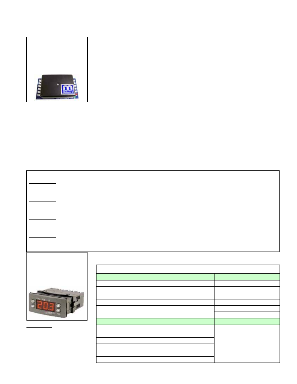
8.2.6 Optional
Electronic Modulation
FIGURE 46B -
Amplifier in Options
AG8 (P/N 260864);
AG9 and AG9H (P/N
260863 for both)