0 controls and operation – Reznor SHH (Indoor PreevA) Unit Installation Manual User Manual
Page 51
Form I-PDH/SDH/PEH/SHH/PXH, Page 51
8.0 Controls and
Operation
8.1 Gas Controls - apply to Models PDH, SDH, and SHH
All gas-fired furnaces are equipped with a 24-volt combination valve which includes
the automatic electric on-off valve the pressure regulator, the safety pilot valve, and
the manual shutoff valve. Valve on/off function is controlled by the room thermostat or
digital controller.
8.2 Analog Controls
for Heating or
Heating/Makeup
Air
8.2.2 Two-Stage
Operation -
Recirculated Heating
Only (Option AG2
applies to Models
PDH, SDH, and SHH;
Option EG2 applies to
Model PEH)
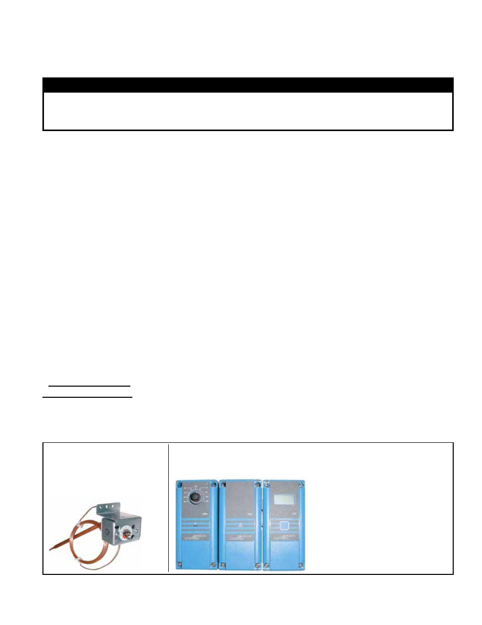
FIGURE 43 - Unit-mounted
Ductstat, P/N 211481, in
Options AG3 and AG60
Factory
set at
70°F
FIGURE 44 - Remote Temperature Selector, Stage-Adder Module,
and Optional Display Module for Ductstat Control in Two-Stage
Makeup Air Control Options (Option AG15, AG16, AG61, and AG62)
(A) Temperature Selector,
P/N 115848;
(B) Stage Adder,
P/N 115849;
(C) Display Module,
P/N 115852
(A)
(B)
(C)
8.2.3 Two-Stage
Operation - Makeup
Air Heating Only
Application (Option
AG3, AG15, or AG16)
- applies to Models
PDH, SDH, and SHH
Two-stage makeup air units are equipped with a two-stage gas valve, but instead of
control from a two-stage room thermostat, the outlet air temperature is monitored and
controlled by a two-stage ductstat. When the discharge air temperature drops to the
setpoint, factory-set low fire is energized. If low fire (70%) cannot satisfy the ductstat
setting, high fire (100%) is energized.
A makeup air application is usually adjusted to discharge an outlet air temperature
between 65°F and 75°F. In all applications, the allowable temperature rise of the fur-
nace in the installation dictates the limits of the ductstat temperature setting.
Depending on the option selected, the factory-installed sensor is either field-connected
by capillary tubing to the unit-mounted ductstat (
FIGURE 43) or electrically connected
to a remote electronic temperature selector (
FIGURE 44). The remote temperature
selector with stage adder is available with or without a display module.
On gas-fired Models PDH, SDH, and SHH, a two-stage combination gas control valve
provides for low fire (70%) or high fire (100%) operation controlled by a two-stage ther-
mostat. First stage (low fire) is factory set. Both high and low stages are controlled by
a Servo regulator, maintaining constant gas input under wide variations in gas supply
pressure. See instructions packed with the unit for specific gas valve specifications,
wiring, and operating instructions.
On electric heat Model PEH, staging of heat from the heating elements is controlled by
the two-stage thermostat.
A two-stage thermostat is supplied as an option or may be field supplied. Follow the
manufacturer’s instructions and the wiring diagram.
8.2.1 Single-Stage Operation - Recirculated Heating Only (Option
AG1 applies to Models PDH, SDH, and SHH; Option EG1 applies to
Model PEH)
The single-stage gas valve on Model PDH, SDH, or SHH allows for single-stage con-
trol from a single-stage, 24-volt thermostat. On Model PEH, the heating elements are
controlled by a single-stage, 24-volt thermostat. The thermostat is either provided as
an option or field supplied. Follow the thermostat manufacturer’s instructions for instal-
lation. Make wire connections according to the wiring diagram.
WARNING
The operating valve is the prime safety shutoff. All gas supply lines must be free
of dirt or scale before connecting the unit to ensure positive closure. See Hazard
Levels, page 2.
Optional Unit-Mounted Ductstat with Capillary Tubing (Option AG3) - The control
illustrated in
FIGURE 43 has an adjustable range from 50° to 120°F with a fixed differ-