0 electrical supply and wiring, 2 supply wiring 7.1 general, 2 supply wiring – Reznor SHH (Indoor PreevA) Unit Installation Manual User Manual
Page 43: 1 general, Table 28b - supply wiring size - model peh
Form I-PDH/SDH/PEH/SHH/PXH, Page 43
7.0 Electrical
Supply and
Wiring
All electrical wiring and connections including electrical grounding must be made in
accordance with the National Electric Code ANSI/NFPA No. 70 (latest edition); or in
Canada, the Canadian Electrical Code, Part I-C.S.A. Standard C22.l. Check any local
ordinances or utility company requirements that apply.
7.2 Supply Wiring
Check the rating plate on the heater for the supply voltage and the current require-
ments. A separate line voltage supply with fused disconnect switch should be run
directly from the main electrical panel to the unit, making connections in the electrical
compartment. Supply wiring enters the cabinet on the control side below the electrical
compartment door (PDH/SDH/SHH/PXH), on the control post (PEH), or in line directly
below through the base (PDH/SDH/PEH/SHH/PXH). Before turning on the power,
check and tighten all electrical terminals.
Seal all electrical entrance openings with
field-supplied bushings.
7.1 General
NOTE: If the system has an
optional convenience outlet
or UVC light, both of those
options require a separate
115 volt power supply.
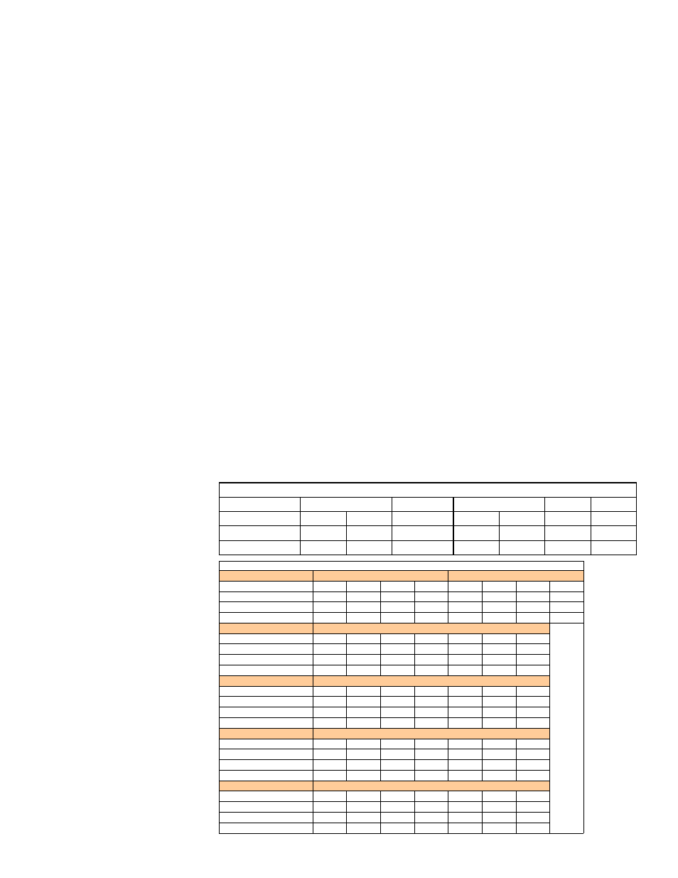
TABLE 28A - Supply
Wiring Size - Models
PDH, SDH, PXH, and
SHH
Field-Supplied THHN, THWN or THWN-2 Wiring and Conduit Minimum Size for Model PEH
Voltage/Phase
208/1
230/1
KW
10
15
20
30
10
15
20
30
Ampacity
74
96
119
164
78
104
130
182
75°C Wire Gauge
#4
#3
#1
#2/0
#4
#2
#1
#3/0
Conduit Trade Size
1
1
1-1/4
1-1/2
1
1
1-1/4
2
Voltage/Phase
208/3
KW
20
30
40
60
80
90
120
Ampacity
66
92
118
142
184
205
267
75°C Wire Gauge
#4
#3
#1
#1/0
#3/0
#4/0
300kcmil
Conduit Trade Size
1
1-1/4
1-1/2
1-1/2
2
2
2-1/2
Voltage/Phase
230/3
KW
20
30
40
60
80
90
120
Ampacity
74
104
134
161
209
233
305
75°C Wire Gauge
#4
#2
#1/0
#2/0
#4/0
250kcmil 350kcmil
Conduit Trade Size
1
1-1/4
1-1/2
2
2
2-1/2
3
Voltage/Phase
460/3
KW
20
30
40
60
80
90
120
Ampacity
37
52
67
81
105
117
153
75°C Wire Gauge
#8
#6
#4
#4
#2
#1
#2/0
Conduit Trade Size
3/4
3/4
1
1
1-1/4
1-1/2
2
Voltage/Phase
575/3
KW
20
30
40
60
80
90
120
Ampacity
31
44
56
67
88
98
128
75°C Wire Gauge
#10
#8
#6
#4
#3
#3
#1
Conduit Trade Size
1/2
3/4
3/4
1
1-1/4
1-1/4
1-1/2
TABLE 28B - Supply
Wiring Size - Model
PEH
60 hertz is the maximum high speed. Maximum speed for low speed heating is the
frequency that will provide the maximum temperature rise of the heater.
Maximum allowable temperature rise for a Model SDH or PDH is 70°F with an alu-
minized heat exchanger or 100°F with a stainless steel heat exchanger. (
NOTE: If
equipped with modulating gas control Option AG40, AG58, DG2, DG6, D12B, or D12G
and a stainless steel heat exchanger, maximum temperature rise of is 120°F.)
Maximum temperature rise for Model SHH is 100°F (Model SHH built prior to 4/13 has
a temperature rise of 70°F.).
Follow the VFD controller manufacturer’s instructions that are packaged with the
heater (in the owner’s envelope) to program the VFD settings. The formula for motor
speed is N=120xf/p where N is speed; f is frequency; and p is number of poles (3600
RPM motor has 2 poles; an 1800 RPM motor has 4 poles).
Example: 1800 RPM motor on 60Hz; N = 120 x 60/4 = 1800
1800 is synchronous speed; assume 2% slip. Motor will run between
1750 and 1790 RPM at full load depending on design.
Run the same motor at 45Hz (120 x 45/4 = 1350). 1350 RPM less 2%
slip equals about 1300 RPM.
Field-Supplied THHN, THWN or THWN-2 Wiring and Conduit Minimum Size - PDH, SDH, PXH, SHH
Voltage/Phase
115/1
208-230/1
208-230/3
460/3
575/3
Motor HP's
1/4 - 1/2
1
1 - 1-1/2
1/4 - 3
5
1/4 - 5
1/2 - 5
Wire Gauge
14
12
14
14
12
14
14
BX Cable
3/8"
3/8"
3/8"
3/8"
3/8"
3/8"
3/8"