0 controls and operation (cont’d) – Reznor SHH (Indoor PreevA) Unit Installation Manual User Manual
Page 54
Form I-PDH/SDH/PEH/SHH/PXH, Page 54
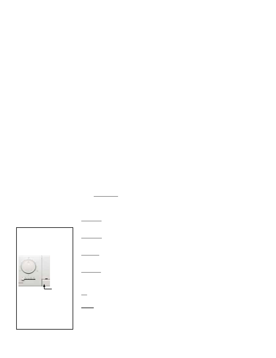
FIGURE 48A - Room
Command Module,
P/N 211423, in Option
DG1 and Option DG2
Push
Button
Provides on-off and
heat/vent/cool mode
selection; room temp-
erature selection; and
has a push button for
unoccupied override.
Sequence of Operation
Options DG1 and DG2 are space temperature control. Options DG5 and DG6 are
discharge air temperature control. With all four options, a wall-mounted sensor and
setpoint dial controls the functionality. With discharge air temperature control (DG5
and DG6), the wall sensor is disabled and a discharge sensor is used to control the
temperature. The wall unit shown in
FIGURE 48A is used with Options DG1 and DG2;
it has a 45°F to 95°F adjustment dial to set the desired space temperature. The wall
unit shown in
FIGURE 48B is used with Options DG5 and DG6; it has a ±6°F warmer/
cooler adjustment dial for the discharge air temperature setpoint. Both wall units have
a mode slider and an unoccupied mode override button. The slider selects the func-
tionality of the unit: Cool Only, Heat Only, Fan Only, Auto Mode, Off.
The dial value will be the working heating or cooling setpoint depending on the mode.
In the
auto mode, the dial is the midpoint value between the cooling and heating set-
point. Example: (variable DB = 2°F default) If the dial is set to 72°F, the cooling and
heating setpoints for unit operation are 70°F and 74°F respectively.
Mode Slider Functions
Cool Only - The unit will allow only the cooling to function. There is an adjustable
parameter “OC” outdoor ambient temperature lockout setting below which mechanical
cooling will not be allowed to operate.
Heat Only - The unit will allow only the heating to function. There is an adjustable
parameter “OH” outdoor ambient temperature setting above which heating will not be
allowed to operate.
Fan Only - The unit will allow only the fan to run. The fan will run only in occupied mode
if the external contact is closed (Binary input #3). If the contact is open, the fan will not
run.
Auto Only - The unit will be allowed to provide heating and cooling, providing the out-
door ambient conditions are met. The heating setpoint and cooling setpoint are con-
trolled by “HSP” and “CSP” settings and the setpoint dial (warmer/cooler adjust or the
Setpoint dial setting), and the value of DB.
Off - The unit will shut down all functionality – neither heating, cooling nor fan will be
allowed to operate.
NOTE: Hold the Enter key on the controller for 15 seconds to access the variable
screens. (SUO should appear.) Use the down arrow to go to SSI. Press the enter but-
ton. If the value is ON, the sensor with the setpoint overlay is active. If the value is OFF,
the sensor with the warmer/cooler adjust should be used. Use the up/down arrows to
toggle between ON/OFF and press the enter button to save. This setting can also be
changed in CommPro (nciWallStatSelect). See the control instruction manual for more
information.
8.3 Digital Controls for Heating/Cooling, Makeup Air and Dehumidification (cont’d)
8.0 Controls and Operation (cont’d)
8.3.1 Optional Digital
Heating/Cooling/
Makeup Air Controls,
Options DG1, DG2,
DG5, DG6 - PDH and
SDH; PXH (cont’d)
Two-Speed Venter System in Options DG1, DG2, DG5, DG6 (also applies
to modulation Option AG40 with field-supplied control)
A proprietary electronically controlled venter system provides the correct quantity of
combustion air to maintain an overall average of 81% thermal efficiency through a
range of gas inputs from 100 to 25 percent for natural gas and through a gas input
range of 100 to 40 percent for propane gas. The venter’s low speed operation is con-
trolled by an electronic board (
FIGURE 45) and a gas pressure switch that senses
outlet gas pressure. The venter is operated at a reduced voltage when the outlet gas
pressure is below 1.7 inches w.c. for natural gas units and for propane units when the
outlet gas pressure is below 5.0 inches w.c.
The proprietary electronically controlled venter system always operates at high speed
during prepurge, postpurge, and the ignition periods. Speed selection occurs after
flame is proven.