3 optional filter rack and filters, Table 14 - filter quantity and sizes – Reznor SHH (Indoor PreevA) Unit Installation Manual User Manual
Page 23
Form I-PDH/SDH/PEH/SHH/PXH, Page 23
6.4.2 Optional Two-
Position Damper with
Duct Flange (factory
installed), Option AR8
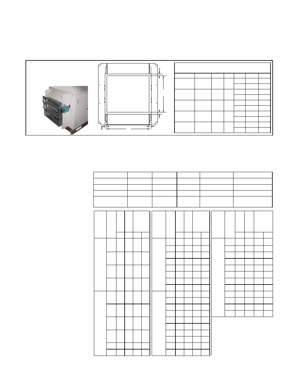
FIGURE 16 - Optional Inlet
Air Two-Position (on/off)
Damper with Duct Flange
(factory installed), Option
AR8
TABLE 13 - Opening Dimensions of Duct Flange
on Optional Inlet Air Damper
PDH/SDH
PEH
SHH PXH
A
B
75/100
10A/
20A/40A
N/A 000A
inches 19-3/8 16-3/4
mm
492
425
125/150
15B/30B/
60B
N/A 000B
inches 24-7/8 16-3/4
mm
632
425
175/200/
225
N/A
130/
180 000C
inches 21-1/4 25-3/4
mm
540
654
250/ 300
30D/60D/
90D/120D 260 000D
inches 34-1/4 18-1/4
mm
870
464
350/400A 40E/80E/
120E
350 000E
inches 38-5/8 21-1/4
mm
981
540
A
B
7/8”
(22mm)
7/8” (22mm)
7/8”
(22mm)
7/8”
(22mm)
Duct Flange
Opening with
Inlet Air Damper
Option AR8
The illustration in
FIGURE 16 shows the two-position damper attached directly to the
blower cabinet. If ordered with a cooling coil module, the damper will be attached
to the inlet air end of the cooling coil module. The damper adds 10” (254mm) to the
length as shown in
FIGURE 2 on page 9. Weight added is in TABLE 5, page 10.
The 7/8” duct flange is part of the damper frame. The inlet air duct should be attached
and sealed. Dimensions for attaching ductwork are shown in
TABLE 13. Ductwork
must have a free area equal to the duct connection.
6.4.3 Optional Filter
Rack and Filters
TABLE 14 - Filter
Quantity and Sizes
(Quantity and width and
height dimensions apply to
all types and thickness of
filters.)
PDH/SDH Sizes
75/100
125/150
175/200/225
250/300
350/400A
PEH Sizes
10A/20A/40A 15B/30B/60B
N/A
30D/60D/90D/120D
40E/80E/120E
SHH Sizes
N/A
N/A
130/180
260
350
PXH Size
000A
000B
000C
000D
000E
Filters - (Qty) Width
x Height in inches
(2)
16 x 25
(2)
20 x 25
(2) 16 x 16;
(2) 16 x 20
(3) 16 x 16;
(3) 16 x 20
(1) 16 x 16; (2) 20 x 20;
(3) 16 x 20
Size
CFM
Disposable
Permanent Aluminum
Pleated
Disposable
Size
CFM
Disposable
Permanent Aluminum
Pleated
Disposable
Size
CFM
Disposable
Permanent Aluminum
Pleated
Disposable
2'' 2'' 2'' 4''
2'' 2'' 2'' 4''
2''
2''
2''
4''
PDH/
SDH
75,
100;
PEH
10A,
20A,
40A;
PXH
000A
569 0.0 0.0 0.0 0.0
PDH/
SDH
175,
200,
225;
SHH
130,
180;
PXH
000C
1329 .1
0.0
.1
0.0
PDH/
SDH
350,
400A;
PEH
40E,
80E,
120E;
SHH
350;
PXH
000E
2657
.1
0.0
.1
0.0
1650 .1
0.0
.1
0.0
3300
.1
0.0
.1
0.0
1000 .1 0.0 .1 0.0
2000 .1
0.0
.1
.1
3500
.1
0.0
.1
.1
2500 .1
.1
.1
.1
4000
.1
0.0
.1
.1
1500 .1 0.0 .1
.1
3000 .1
.1
.2
.1
4500
.1
.1
.1
.1
3500 .2
.1
.2
.2
5000
.1
.1
.2
.1
1898 .1
.1
.2
.1
4000 .2
.1
.3
.2
5500
.2
.1
.2
.1
4271 .2
.1
.3
.2
6000
.2
.1
.2
.1
PDH/
SDH
125,
150;
PEH
15B,
30B,
60B;
PXH
000B
949 0.0 0.0 0.0 0.0
PDH/
SDH
250,
300;
PEH
30D,
60D,
90D,
120D;
SHH
260;
PXH
000D
1898 .1
0.0
.1
0.0
6500
.2
.1
.2
.2
2050 .1
0.0
.1
0.0
7000
.2
.1
.3
.2
1250 .1 0.0 .1 0.0
2500 .1
0.0
.1
0.0
7400
.2
.1
.3
.2
3000 .1
0.0
.1
.1
7593
.3
.1
.3
.2
1500 .1 0.0 .1 0.0
3500 .1
0.0
.1
.1
4000 .1
.1
.1
.1
2000 .1 0.0 .1
.1
4500 .1
.1
.2
.1
5000 .2
.1
.2
.1
2500 .1
.1
.2
.1
5500 .2
.1
.2
.2
2847 .2
.1
.2
.1
5694 .2
.1
.3
.2
Filter rack and filters are factory-installed optional equipment. Depending on which
option was ordered, filters may be 1” or 2” disposable, 1”, 2”, or 4” pleated disposable,
or 1” or 2” permanent. If the system does not have an optional cooling coil module, the
vertical filter rack is located in the entering air side of the blower cabinet. If the system
has an optional draw-through cooling coil module, the filter rack is located in the enter-
ing air side of the cooling coil module.
TABLE 15 - Pressure
Drops for Clean Factory-
Installed Filters by Type
and Size (“w.c.)