Reznor SHH (Indoor PreevA) Unit Installation Manual User Manual
Page 39
Form I-PDH/SDH/PEH/SHH/PXH, Page 39
TABLE 24 - Sensor
Data for Johnson A99
Series Temperature
Sensors used in digital
controls - Resistance
VS Temperature
°F
°C
Ohms
-40
-40
613
-31
-35
640
-22
-30
668
-13
-25
697
-4
-20
727
5
-15
758
14
-10
789
23
-5
822
32
-0
855
41
5
889
50
10
924
59
15
960
68
20
997
77
25
1035
86
30
1074
59
35
1113
104
40
1153
113
45
1195
122
50
1237
131
50
1279
140
60
1323
149
65
1368
158
70
1413
167
75
1459
176
80
1506
185
85
1554
194
90
1602
203
95
1652
212
100
1702
221
105
1753
230
110
1804
239
115
1856
248
120
1908
Do not mount the sensor in the ductwork after a split in the supply as that will
cause loss of control in the duct that does not house the sensor.
3. The position of the sensor holder is important. The holder will extend 9-3/16”
(233mm) into the ductwork.
In horizontal ductwork, locate the sensor assembly in the top, middle of the duct
with the sensor probe extending vertically down into the center of the airstream.
In vertical ductwork, locate the sensor assembly in the middle of the side of the
duct that corresponds with the top middle of the discharge outlet.
Turn the holder so that the element will be shielded from direct airflow and will
sense the air temperature as it flows through the holes in the holder.
At the selected location in the ductwork, mark the diamond-shaped hole required
for the sensor holder. Cut the hole no larger than required, approximately 1” x 1”
(25mm x 25mm).
4. The procedure for installing the sensor and attaching the holder depends on
whether the sensor is a capillary or an electrical sensor. Follow the instructions
that apply.
Capillary Sensor (Option AG3 and AG60) - Locate the sensor capillary and run
it out through the hole in the discharge panel of the heater. Determine where the
sensor capillary should enter the box and remove the knockout. Put the capillary
through the hole and secure the bulb to the clip in the holder. Slide the holder into
the ductwork. Using four field-supplied No. 6 sheetmetal screws, attach the box
portion of the holder to the ductwork. Attach the box cover.
Sensor with Wire (Options AG15, AG16, AG58, AG61, AG62, DG5, DG6, D12B,
D12C, D12D, D12E, D12F, and D12G and field-supplied sensor for Option AG40)
- Push the element into the clip in the holder. Determine where the sensor wire
should enter the box and remove the knockout. Slide the holder into the ductwork.
Using four field-supplied No. 6 sheetmetal screws, attach the box portion of the
holder to the ductwork. Attach a field-supplied cable connector to the box, connect
the sensor wire, and attach the box cover.
If sensor is digital, follow the wiring instructions above.
To test the accuracy of the sensor, measure the ohms. Refer to
TABLE 24 (left) to
find the corresponding temperature.
Instructions for Installing Discharge Air Sensor Holder on the Unit -
applies only to Models PDH, SDH, PXH, and SHH without ductwork
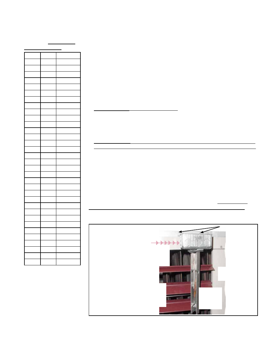
1. Installation requires the discharge air sensor holder (FIGURE 32) and the bracket
in
FIGURE 33. (If attached, remove box cover; it will not be used.)
Attach the
bracket
to the box
and the
front of the
heater.
Holder must
be in this
orientation.
Sensor
Element
in Clip
Center post of
a Size 350
Run the capillary
or wire across top
front of the heater.
FIGURE 33 - Discharge Air
Sensor Holder, P/N 115850,
and Bracket, P/N 213612
2. Select a location for the box on the front near the center of the heater. Orientation
of the sensor holder is important. Position the box so that the element will be
sensing the air temperature as it flows through the holes in the holder.