0 mechanical (cont’d), 1 supply and drain water connections – Reznor SHH (Indoor PreevA) Unit Installation Manual User Manual
Page 30
Form I-PDH/SDH/PEH/SHH/PXH, Page 30
6.5.1 Supply and Drain Water Connections
Water Supply - Connect the water supply to the 1/2” NPT male connection on the
control side of the evaporative cooling module. See location in
FIGURE 21. Install a
manual water shutoff valve upstream of the cooling module inlet at a convenient non-
freezing location. If necessary, install a bleed line between the manual valve and the
cooling module to allow drainage of the line between the shutoff valve and the cooling
module.
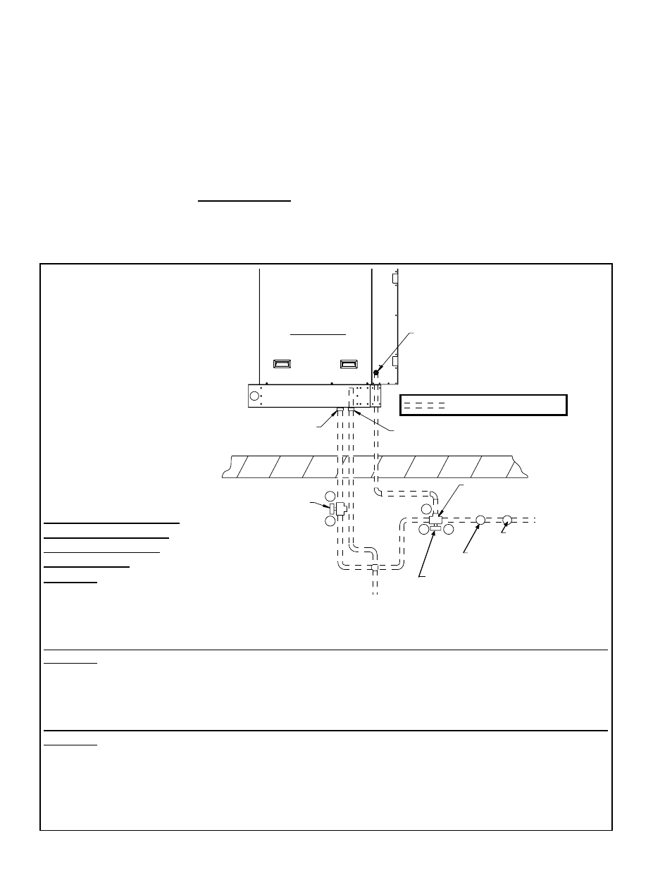
Fill and Drain Kits (field installed) - If the module has a pump and float water control
system and is ordered with a fill and drain kit (Option CT1, CT2, or CT3), refer to the
illustration in
FIGURE 22 to install the automatic fill and drain valves. Refer to the sys-
tem wiring diagram to make wiring connections.
Freeze Protection - If a freeze protection option was ordered, the fill valve will not
operate at subfreezing temperature.
NOTE: On an evaporative cooling module with a
recirculating pump and float water control system, freeze protection is only available if
an optional fill and drain kit is field installed. See
Sequence of Operation Section in
FIGURE 22.
Evaporative
Cooling
Module
(factory attached)
Inlet Water Connection
(1/2 male NPT fitting)
Overflow Fitting
3/4 male NPT tapped
with 1/2 female NPT
Drain Fitting
3/4 male NPT tapped
with 1/2 female NPT
2-Way Solenoid Valve
(normally open)
1/2 female NPT
(A 2-way valve is in
Options CT1, CT2, and CT3.
Option CT6 requires
Option CT1, CT2, or CT3.)
To Drain
3-Way Solenoid Valve (valve is suitable for
a maximum close-off pressure differential
of 25 psi and a system static pressure of 300
psi) - 1/2 NPT, 2-position spring return
(normally closed at B port)
(A 3-way valve is in Options CT1, CT2, CT3,
and CT5. Option CT6 requires Option CT1,
CT2, or CT3.)
Actuator must be above the
valve body when mounted
in horizontal piping.
Roof
Water Inlet
Field-supplied
Service Valve
Field-supplied Pressure
Regulator (if required)
A
A
B
B
C
= Field-installed Water Piping
Left Side View
FIGURE 22 - Field-installed
Fill and Drain Valves for
Pump and Float System
(Option CT1, CT2, or CT3)
and
Freeze Protection Kits
(Option CT5 for AquaSaver
and Option CT6 for Pump
and Float System)
Sequence of Operation
with Optional Fill and
Drain and/or Freeze
Protection Kits
Applies to: Float and Pump System with Optional
Fill and Drain Kit (Option CT1, CT2, or CT3)
1) Call for cooling.
2) 2-way valve is energized and closes B to A.
3) 3-way valve is energized opening B to C and closing A to C.
4) During no call for cooling, valves return to normal state.
Applies to: AquaSaver Timed Water System with Optional Freeze Protection (Option CT5)
1) Call for cooling.
2) 3-way valve is energized opening B to C and closing A to C.
3) If outside air temperature drops below freeze protection controller setting, 3-way valve is de-energized and
AquaSaver 24V solenoid valve remains energized for eight minutes to allow complete system water drainage.
4) During no call for cooling, 3-way valve returns to normal state.
Applies to: Float and Pump System with Optional Fill and Drain Kit (Option CT1, CT2, or CT3) and Freeze
Protection (Option CT6)
1) Call for cooling.
2) 2-way valve is energized and closes B to A.
3) 3-way valve is energized opening B to C and closing A to C.
4) If outside air temperature drops below freeze protection controller setting, valves return to normal state.
5) During no call for cooling, valves return to normal state.
6.0 Mechanical
(cont’d)
6.5 Optional
Evaporative
Cooling
Module (factory
installed) -
Models PDH,
SDH, PEH, PXH
(cont’d)