Reznor SHH (Indoor PreevA) Unit Installation Manual User Manual
Page 31
Form I-PDH/SDH/PEH/SHH/PXH, Page 31
Overflow and Drain - All cooling modules are equipped with an overflow and drain
fitting. The fittings are in the cabinet bottom and come complete with a lock nut and
a sealing gasket. Check these fittings for tightness before installing the overflow and
drain piping. The drain and overflow fitting will accommodate 3/4” NPT fittings and are
also tapped with a 1/2” female pipe thread for iron pipe.
Bleed Off - If the module has a recirculating pump and float water control sys-
tem, it has a bleed off hose. The bleed off hose is attached to a tee in the fill line and
must drain into the overflow drain. Make sure that the end of the bleed off line extends
into the overflow drain. Adequate bleed off is important to maintaining an efficiently
operating system by lessening the concentration of undesirable minerals in the water
being circulated through the cooling module. Minerals buildup because evaporation
only releases “pure water vapor” causing the concentration of contaminants in the
water to increase as the evaporation process continues. The minerals accumulate on
the media, in the water lines, on the pump, and in the reservoir.
CAUTION: Water reservoir must be drained and pump motor
turned off when outside temperature falls below 32°F (0°C).
Pump must never be operated without water in the reservoir. See
Hazard Levels,page 2.
Water Hammer Arrestor - If the cooling module is equipped with an AquaSaver
timed metering system, the operation of the solenoid valve in the water line is con-
trolled by the timer. Due to various water pressures and installation conditions, the
water supply line may bang abruptly when the solenoid valve closes. This banging
can be minimized by installing an optional water hammer arrestor (Option ECB1) in
the supply line. When installing an optional water hammer arrestor, select an indoor
location (above 32°F), either horizontal or vertical, in line with and as close to the
solenoid valve as possible. Follow the manufacturer’s instructions to install and main-
tain the water hammer arrestor.
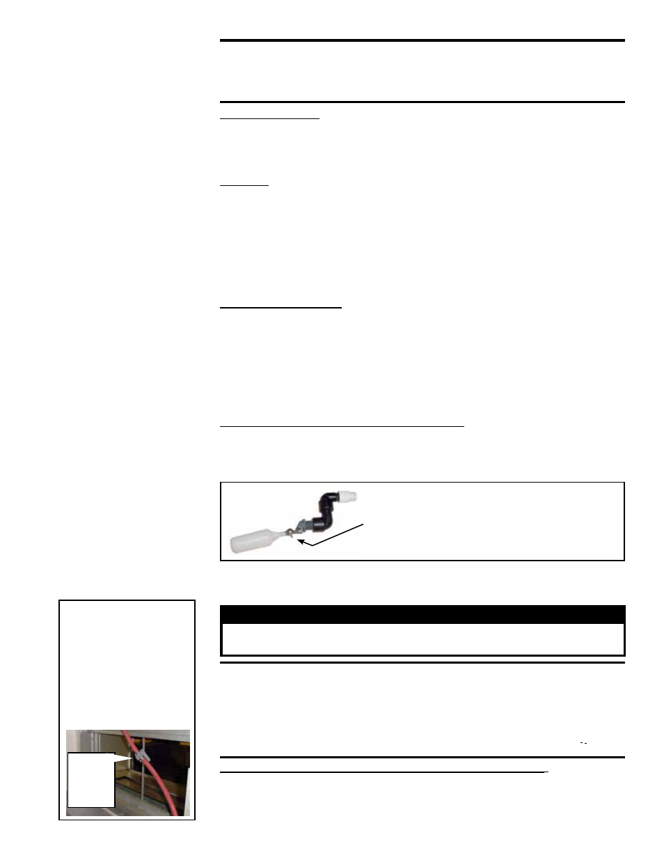
Recirculating Float and Pump Control System - Turn on the water supply and
check for good flow. When the float valve (
FIGURE 23) shuts off the water supply,
measure the water depth. The depth of the water should be approximately 3” (76mm).
If necessary, adjust the position of the float valve with the wing nut to obtain the proper
water level.
Adjust the float valve position with the wing nut
to maintain approximately 3” (76mm) of water in
the reservoir
.
1/2” MPT Water Supply Connection
FIGURE 23 - Float
Valve, P/N 216553
6.5.2 Adjusting Water
Flow Over Pads
Proper water flow over the evaporative cooling media is critical to extend the life and
maintain the
efficiency of the pads. To adjust the flow, read the warnings and follow
the instructions that apply.
WARNING
Adjust ball valve only when the power is disconnected from the system.
Failure to do so can cause electrical shock, personal injury, or death.
CAUTION: Do not flood the media pads with extreme quantities of
water for long periods as this will cause premature breakdown of
the media. An even flow from top to bottom of the media with the
least amount of water is all that is required to assure maximum
efficiency and media life span. More water does not provide more
evaporation or more cooling.
Adjusting Water Flow with a Float and Pump Control System - Using the ball
valve, located in the length of hose running from the pump to the distribution line inlet
(See
FIGURE 24), adjust the valve handle to allow the flow to completely dampen the
media pads from top to bottom.
FIGURE 24 - Remove
side door and locate
ball valve (illustration
below is from the
rear). Both water flow
control systems have
a ball valve in the
water line.
Ball
Valve,
P/N
207468