0 mechanical (cont’d) – Reznor SHH (Indoor PreevA) Unit Installation Manual User Manual
Page 16
Form I-PDH/SDH/PEH/SHH/PXH, Page 16
INSTRUCTIONS for ELECTRONIC MODULATION Gas Control Options AG58 and
D12G)
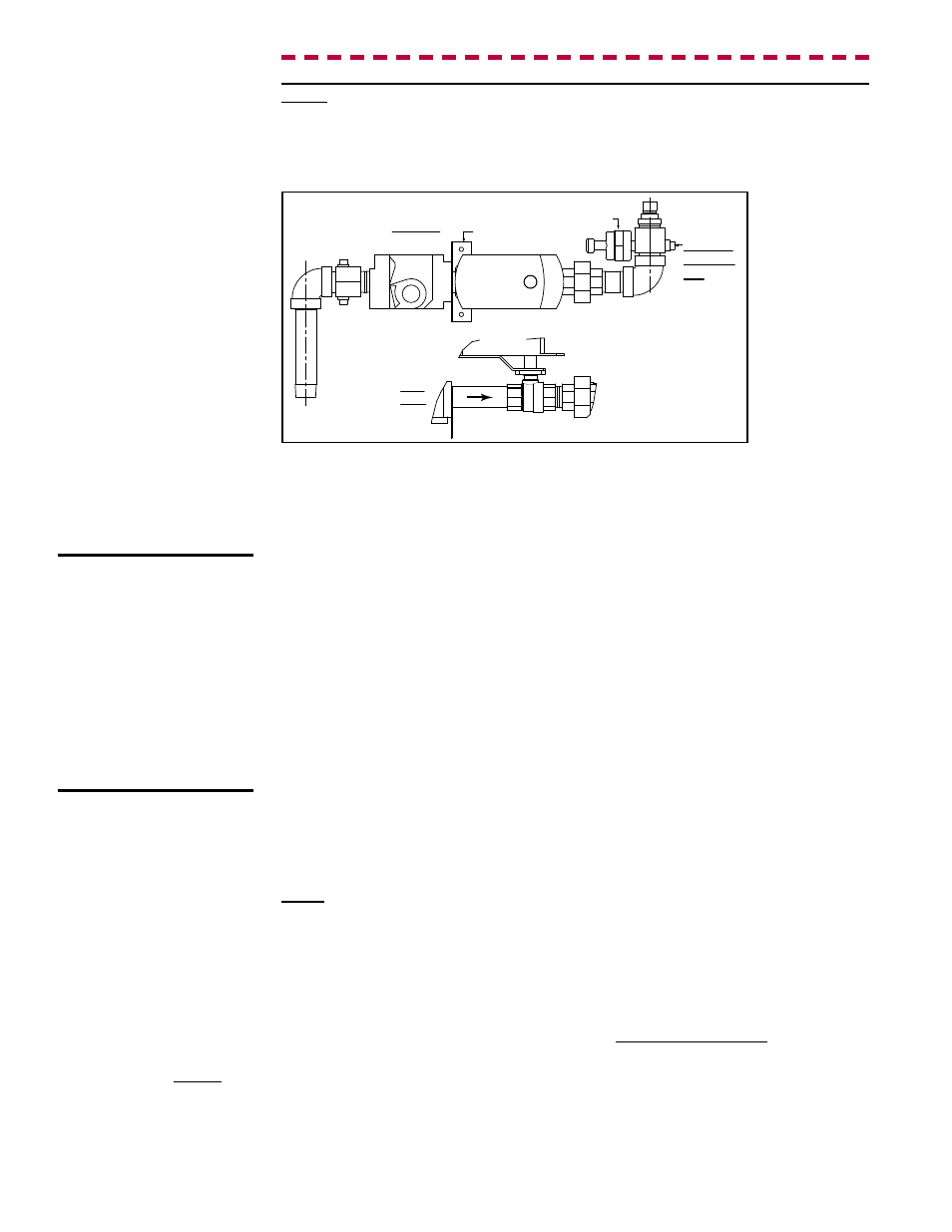
1) Measure the Manifold Pressure
Turn the manual valve in the gas line off.
Locate the manifold pressure tap; see
FIGURE 9. Remove the bushing and connect a
manometer to the 1/8" pressure tap.
Top View
Side
View
Ball Valve
Actuator
Ball Valve
Actuator
Combination
Single-Stage
Gas Valve
Pressure
Tranducer
Ball Valve
Gas Valve
Bracket
Orifice
Manifold
Pressure
Tap
FIGURE 9 - Gas
Manifold with Gas
Control Options AG58
and D12G
High Altitude Operation
If the heater is being installed at an elevation above 2000 ft (610M), check the rat-
ing plate to verify that the heater is factory-equipped for the elevation at the installation
site.
If the elevation on the rating plate matches the elevation of the installation
site, field adjustment for high altitude is not required.
If the rating plate does not match the elevation of the installation site, high altitude
adjustment will need to be done as part of the startup procedure. (High altitude adjust-
ment can only be done while the unit is operating.) During startup, follow the instruc-
tions in this section to adjust the valve outlet pressure.
Turn on the manual gas valve. Operate the unit with a call for heat. Verify that the
actuator has fully opened the ball valve (highest fire). The ball valve is fully open when
the dash marks on the actuator are aligned with the gas piping. With the burner at high-
est fire, measure the manifold pressure. The manifold pressure should be 3.4" w.c. for
natural gas or 10” w.c. for propane.
2) Adjust Pressure at the Single-Stage Valve (if needed)
Turn the manual gas valve off. On the single-stage gas valve (see FIGURE 6, page
14), locate the 1/8” output pressure tap and attach a manometer.
Turn on the manual gas valve. Operate the unit with a call for heat. Check the outlet
pressure of the valve with the burner at full fire. Pressure should be 3.5” w.c for natural
gas or 10” w.c. for propane.
If adjustment is necessary, remove the cap from the
adjustment screw. Set pressures to correct setting by turning the regulator screws IN
(clockwise) to increase pressure. Turn regulator screws OUT (counterclockwise) to
decrease pressure.
After an adjustment is made, cycle the heat section. Re-check the outlet pressure of
the valve and the manifold pressure. When pressure is correct for highest fire, remove
the manometers and replace the caps. Check for a leak at the pressure tap fittings.
3) Lowest fire manifold pressure is regulated by the ball valve actuator in response to
signals from the ignition control board. The ball valve was set at the factory and should
not need to be checked at startup. For future reference, instructions for checking low-
est fire pressure are in the operation/maintenance/service manual (
Form O-PREEVA
& SHH) included in the literature bag.
CAUTION: DO NOT
bottom out the gas
valve regulator
adjusting screw.
This can result
in unregulated
manifold pressure
causing excess
overfire and heat
exchanger failure.
NOTE: Modulating gas control Options AG58 and D12G DO NOT require a gas pres-
sure adjustment derate for high altitude. The patented control system works on a prin-
ciple of safe, continuous gas and combustion air monitoring and adjustment. As the
mass flow through the combustion system changes, due to the lower oxygen level at
high altitude, the control system senses the change, automatically reducing the firing
rate of the burner.
6.1.3 High Altitude
Operation - Gas-Fired
Model PDH, SDH, or
SHH being installed
above 2000 ft (610M)
(Adjustment does NOT
apply to Model SHH with
Gas Control Option AG58
or D12G -- see NOTE on
the right.)
6.0 Mechanical
(cont’d)
6.1 Gas Heat
Section Piping
and Pressure
- Models PDH,
SDH, and SHH
(cont’d)