0 mechanical (cont’d) – Reznor SHH (Indoor PreevA) Unit Installation Manual User Manual
Page 14
Form I-PDH/SDH/PEH/SHH/PXH, Page 14
6.1.2 Checking Gas Pressure
NOTE: If unsure of the
Gas Control Option Code
(AG1, AG2, AG3, AG8,
AG9, AG9H, AG15, AG16,
AG40, AG58, AG60, AG61,
AG62, DG1, DG2, DG5,
DG6, D12B, D12C, D12F,
or D12G), check the wiring
diagram on the heater.
All option codes affected
by electrical power are
listed on the bottom of the
wiring diagram after the
unit Model and Size.
Inlet Pressure (applies to all gas controls)
Before attempting to measure or adjust valve outlet gas pressure, the inlet (supply)
pressure must be within the specified range both when the heater is in operation and
on standby. Incorrect inlet (supply) pressure could cause excessive outlet gas pres-
sure immediately or at some future time. If natural gas inlet (supply) pressure is too
high, install a regulator in the supply line before it reaches the heater. If natural gas
supply pressure is too low, contact your gas supplier.
Inlet pressure to the valve for natural gas must be a minimum of 5” w.c. or as noted
on the rating plate and a maximum of 14” w.c. Inlet supply pressure to the valve for
propane gas must be a minimum of 11” w.c. and a maximum of 14” w.c.
Manifold Pressure at the Burner Orifice
Measuring manifold gas pressure cannot be done until the heater is in operation. It is
included in the “Check After Startup” steps, Paragraph 9.3. The procedure required
depends on the type of gas control option:
• Single and Two Stage Options
AG1, AG2, AG3, AG15, AG16, AG60, AG61,
AG62, DG1, DG5, D12C, D12F - Follow INSTRUCTIONS beginning below.
• Electronic Modulation (2:1 turndown) Options AG8, AG9, AG9H - Follow
instructions on page 15.
• Electronic Modulation (4:1 turndown) Options AG40, DG2, DG6, D12B -
Follow instructions on page 15.
• Electronic Modulation (8:1 turndown) Options AG58, D12G - Follow
instructions on page 16.
All gas pressure measurements should be done with a manometer (fluid-filled gauge)
rather than a spring type gauge due to the difficulty of maintaining calibration. Use a
water column manometer readable to the nearest tenth of an inch.
INSTRUCTIONS for single-stage and two-stage gas control options (Options
AG1, AG2, AG3, AG15, AG16, AG60, AG61, AG62, DG1, DG5, D12C, D12F)
The outlet pressure is regulated by the combination gas valve. The combination valve
outlet pressure should be as shown in
TABLE 10, page 17, (for the model size, gas
type, gas control option, and altitude of the installation) or as noted on the rating plate.
1) Gas Valve Pressure Tap Locations
Locate the 1/8” outlet pressure tap on the single or two-stage valve (See
FIGURE
6). With the manual valve turned off to prevent flow to the gas valve, connect a
manometer to the 1/8” pipe outlet pressure tap in the valve. Both high-fire and low-
fire outlet pressure can be checked at this pressure tap.
2) Measure Outlet Pressure and Adjust (if needed)
Open the manual valve and operate the heater.
Using the manometer connected to the valve, measure the outlet pressure of the
single-stage gas valve or high fire on a two-stage valve. To measure low-stage
pressure on units equipped with a two-stage valve (Options AG2, AG3, AG15, AG16,
AG60, AG61, AG62, DG1, DG5, D12C, and D12F), disconnect the wire from the “HI”
terminal on the valve. Measure gas pressure with the manometer attached to the
valve. Re-connect the wire.
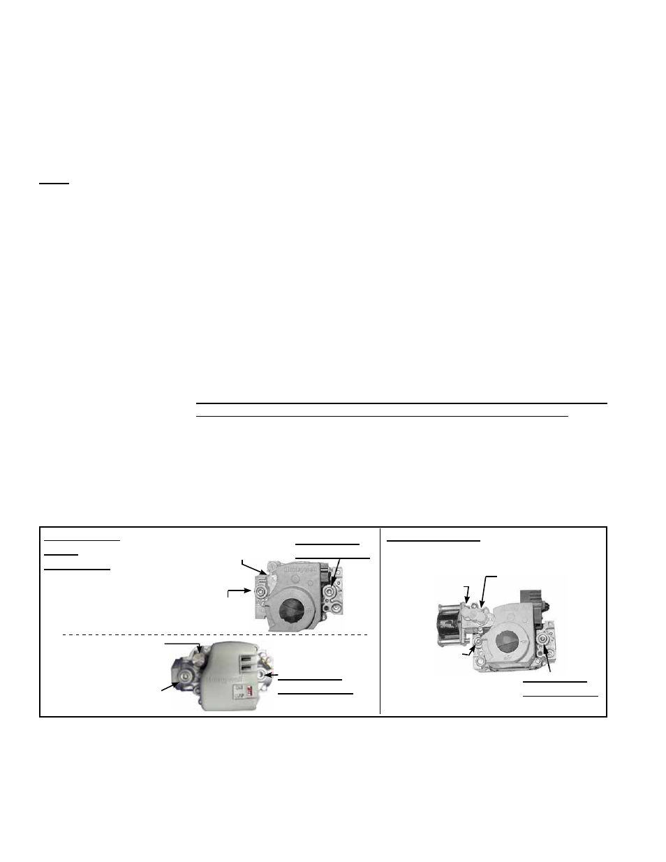
FIGURE 6 - Top Views
of Valves Showing
Outlet Pressure Tap and
Adjustment Locations
6.0 Mechanical
(cont’d)
6.1 Gas Heat
Section Piping
and Pressure
- Models PDH,
SDH, and SHH
(cont’d)
Single-Stage
Valve
(two styles)
1/8” Outlet
Pressure Tap
Adjust Outlet
Pressure
Inlet
Pressure Tap
Two-Stage Valve
Adjust High
Fire Outlet
Pressure
Adjust Low
Fire Outlet
Pressure
Inlet
Pressure
Tap
1/8” Outlet
Pressure Tap
1/8” Outlet
Pressure Tap
Inlet Pressure Tap
Adjust Outlet
Pressure