5 electrical operating components, 1 high temperature limit control - pdh, sdh, shh, Table 31 - pressure switch settings – Reznor SHH (Indoor PreevA) Unit Installation Manual User Manual
Page 47
Form I-PDH/SDH/PEH/SHH/PXH, Page 47
7.5 Electrical
Operating
Components
7.5.1 High Temperature Limit Control - PDH, SDH, SHH
Units are equipped with a temperature activated auto reset capillary-type limit control.
The control is factory set and is non-adjustable. If the setpoint is reached, the limit
control will interrupt the electric supply to the gas valve. This safety device provides
protection in the case of motor failure or lack of airflow due to a restriction at the inlet
or outlet.
CAUTION: The auto reset limit control will continue to shut down the heater until
the cause is corrected. Never bypass the limit control; hazardous conditions could
result. See Hazard Intensity Levels, page 2.
7.5.2 Reverse Airflow
Limit Control - PDH,
SDH, and SHH
Units are equipped with a temperature activated auto reset reverse airflow limit con-
trol. The control is factory set and is non-adjustable. If the setpoint is reached, the limit
control will interrupt the electric supply to the gas valve. This safety device provides
protection in the case of motor failure or lack of airflow due to a restriction at the outlet.
7.5.3 Combustion
Air Pressure Switch
(Air Proving Switch) -
PDH, SDH, and SHH
The combustion air proving switch is a pressure switch that monitors air pressure to
ensure that proper combustion airflow is available. On Model PDH, the switch is a
single pole/normally open device which closes when a negative pressure is sensed
in the venter housing. On separated-combustion Models SDH and SHH, the switch
senses the differential pressure between the negative pressure in the venter housing
and the pressure in the cabinet.
On startup when the heater is cold, the sensing pressure is at the most negative level,
and as the heater and flue system warm up, the sensing pressure becomes less nega-
tive. After the system has reached equilibrium (about 20 minutes), the sensing pres-
sure levels off.
If a restriction or excessive flue length or turns cause the sensing pressure to be out-
side the switch setpoint, the pressure switch will function to shutoff the main burner.
The main burner will remain off until the system has cooled and/or the flue system
resistance is reduced.
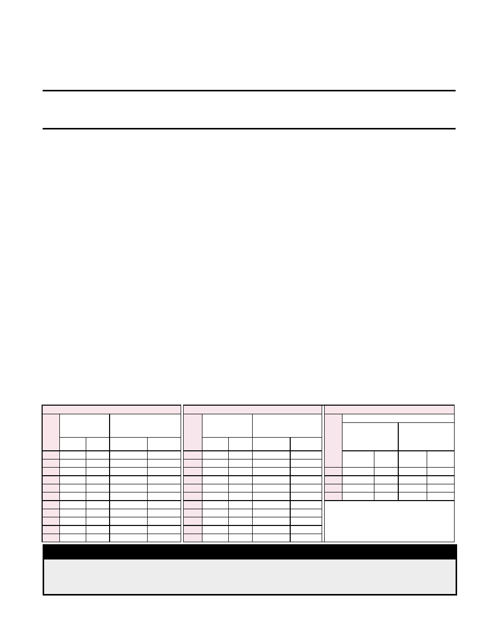
TABLE 31 lists the switch setpoints for sea level operating conditions by model and
size. The high speed settings apply to all units. The low speed settings apply only to
units with a two-speed venter (units with Gas Control Option AG8, AG9, AG9H, AG40,
AG60, AG61, AG62, DG1, DG2, DG5, DG6, D12B, D12C). Models equipped with two-
speed venter motor operation have two combustion air proving switches. When the
venter is operated at high speed, the “high speed” combustion air proving switch moni-
tors the combustion airflow to ensure adequate airflow for safe and efficient operation.
During low speed venter operation, when fuel gas input rate is reduced, a second
“low speed” combustion air proving switch monitors the combustion airflow to ensure
adequate airflow for safe and efficient operation.
NOTE: Above 6000 ft (1830
M) elevation, a high altitude
pressure switch may be
required. See Paragraph
6.1.3.
TABLE 31 - Pressure
Switch Settings
DANGER
Models PDH, SDH, and SHH require proper venting flow. NEVER bypass combustion air
proving switch(es) or attempt to operate the unit without the venter running and the proper
flow in the vent system. Hazardous conditions could result. See Hazard Levels, page 2.
P/N’s & Settings for Model PDH
P/N’s & Settings for Model SDH
P/N’s & Settings for Model SHH
PDH
Size
High Speed
(applies to all gas
controls)
Low Speed (applies only
to units with gas controls
using a 2-speed venter) *
SDH
Size
High Speed
(applies to all gas
controls)
Low Speed (applies only
to units with gas controls
using a 2-speed venter) *
SHH
Size
High Speed
Applies to SHH with
Options AG1, AG2,
AG3, AG15, AG16,
& D12F
Applies to SHH with
Option AG58 & D12G
Switch
P/N
Setting
(" w.c.)
Switch P/N
Setting
(" w.c.)
Switch
P/N
Setting
(" w.c.)
Switch P/N
Setting
(" w.c.)
75
197030
0.40
205442
0.20
75
197030
0.40
205442
0.20
Switch
P/N
Setting
(" w.c.)
Switch
P/N
Setting
(" w.c.)
100
197030
0.40
205444
0.30
100
197030
0.40
205444
0.30
125
196388
0.50
205444
0.30
125
196388
0.50
205444
0.30
130
201161
1.30
201160
1.05
150
197028
0.65
205444
0.30
150
197028
0.65
205444
0.30
180
201161
1.30
201160
1.05
175
201158
1.10
197030
0.40
175
201158
1.10
197030
0.40
260
201159
1.40
201160
1.05
200
201158
1.10
197030
0.40
200
201158
1.10
197030
0.40
350
221228
2.30
221160
1.05
225
201158
1.10
197030
0.40
225
201158
1.10
197030
0.40
* Gas Control Options AG8, AG9, AG9H,
AG40, AG60, AG61, AG62, DG1, DG2, DG5,
DG6, D12B, and D12C.
250
201158
1.10
197030
0.40
250
201158
1.10
197030
0.40
300
201158
1.10
197030
0.40
300
201158
1.10
197030
0.40
350
201158
1.10
197030
0.40
350
201158
1.10
197030
0.40
400A
201158
1.10
197030
0.40
400A
201158
1.10
197030
0.40