Reznor SHH (Indoor PreevA) Unit Installation Manual User Manual
Page 15
Form I-PDH/SDH/PEH/SHH/PXH, Page 15
Modulating Valve in
Options AG8, AG9,
AG9H, AG40, DG2,
DG6, and D12B -- DO
NOT adjust.
CAUTION: DO NOT
bottom out the gas
valve regulator
adjusting screw.
This can result
in unregulated
manifold pressure
causing excess
overfire and heat
exchanger failure.
To ensure an accurate high fire
reading at the single-stage valve, a
minimum signal of 20VDC must be
present at the modulating valve.
FIGURE 7 - Top View
of Modulating Valve in
AG8, AG9, AG9H, AG40,
DG2, DG6, and D12B
Normally, when operating at the altitude indicated on the rating plate,
adjustments to the factory settings should not be necessary. If adjustment is
required, remove the cap from the adjustment screw on the single or two-stage valve.
Adjust pressure setting by turning the regulator screw IN (clockwise) to increase
pressure. Turn regulator screw OUT (counterclockwise) to decrease pressure. If
an adjustment is made, turn up the thermostat. Cycle the burner once or twice to
properly seat the adjustment spring in the valve. Re-check the pressure. When the
outlet pressure is right for the installation, remove the manometer and replace the
cap. Check for a leak at the pressure tap fitting.
WARNING
Valve outlet gas pressure must never exceed the value listed in
TABLE 10 (or as shown on the rating plate).
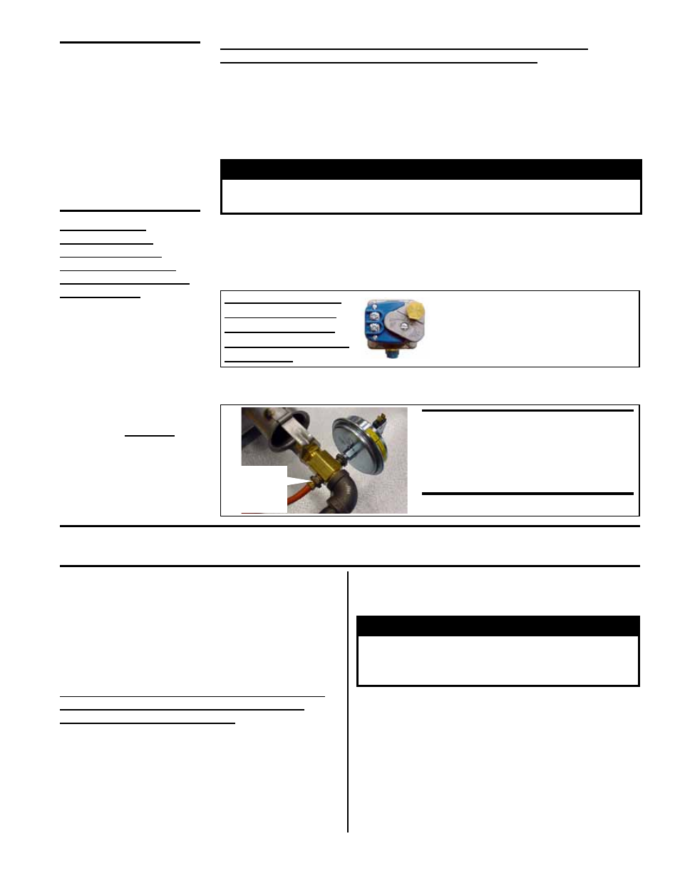
To check low-fire (bypass pressure), locate the 1/4” NPT pressure tap behind the
orifice adapter as shown in
FIGURE 8. Connect a manometer to the 1/4” pressure tap.
FIGURE 8 - Pressure
Tap Location for
Measuring Low Fire
Outlet (Bypass)
Pressure -- Electronic
Modulation Gas Control
Options AG8, AG9,
AG9H, AG40, DG2, DG6,
and D12B
WARNING:
Measure low-fire
pressure at this location only for
units with electronic modulation
gas control Option AG8, AG9,
AG9H, AG40, DG2, DG6, or D12B).
1/4” NPT
Pressure
Tap
2) Measure High Fire Pressure and Adjust (if
needed)
Open the manual valve and operate the heater.
Using the manometer connected to the single-stage
valve, measure the outlet pressure. To ensure an
accurate high-fire gas pressure reading at the single-
stage valve, a minimum 20VDC signal MUST be present
at the modulating gas valve.
Normally, when operating at the altitude indicated
on the rating plate, adjustments to the factory
settings should not be necessary. If adjustment is
required, remove the cap from the adjustment screw
on the single-stage valve. Adjust pressure setting by
turning the regulator screw IN (clockwise) to increase
pressure. Turn regulator screw OUT (counterclockwise)
to decrease pressure. If an adjustment is made, turn up
the thermostat. Cycle the burner once or twice to properly
seat the adjustment spring in the valve. Re-check the
pressure. When the outlet pressure is right for the
installation, remove the manometer and replace the cap.
Check for a leak at the pressure tap fitting.
WARNING
Valve outlet gas pressure must never
exceed the value listed in TABLE 10, page
17, (or as shown on the rating plate).
3) Measure Low Fire (Bypass) Pressure
To measure low-fire (bypass pressure) on electronic
modulation gas control Options AG8, AG9, AG9H, AG40,
DG2, DG6, and D12B, disconnect one of the wire leads
to the modulating valve. Measure the pressure with the
manometer attached to the pressure tap just behind the
orifice adapter (
FIGURE 8). Re-connect the wire.
DO NOT attempt to adjust the bypass (low-fire) pressure.
If bypass pressure is incorrect (see
TABLE 10, page 17),
contact the factory.
CAUTION: DO NOT bottom out the gas valve regulator adjusting screw. This can result in
unregulated manifold pressure causing excess overfire and heat exchanger failure.
INSTRUCTIONS
for ELECTRONIC
MODULATION Gas
Control Options AG8,
AG9, AG9H, AG40, DG2,
DG6, and D12B
1) Gas Valve and Manifold Pressure Tap Locations
The manifold includes a single-stage valve and a modulating valve (
FIGURE 7).
Locate the outlet pressure tap just behind the orifice adapter (See
FIGURE 6). To
check high fire outlet pressure, connect a manometer to the outlet pressure tap just
behind the orifice adapter.