Interlogix NS3702-24P-4S User Manual User Manual
Page 381
381
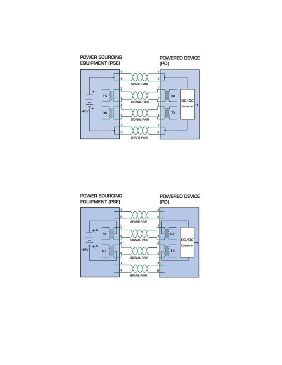
specification allows two options for using these cables for power, shown in Figure 1 and Figure 2:
The spare pairs are used. Figure 1 shows the pair on pins 4 and 5 connected together and forming the positive supply, and the pair
on pins 7 and 8 connected and forming the negative supply. (In fact, a late change to the spec allows either polarity to be used).
Figure 8-1:
Power Supplied over the Spare Pins
The data pairs are used. Since Ethernet pairs are transformer coupled at each end, it is possible to apply DC power to the center tap
of the isolation transformer without upsetting the data transfer. In this mode of operation the pair on pins 3 and 6 and the pair on pins
1 and 2 can be of either polarity.
Figure 8-2:
Power Supplied over the Data Pins
- 600-1053-4 (12 pages)
- NX-590NE (38 pages)
- NX-591NE-GSM (16 pages)
- NX-592E (13 pages)
- Simon XT CDMA Module V4 (9 pages)
- Simon XT GSM Module V4 (10 pages)
- NX-548E (12 pages)
- NX-540E (32 pages)
- D1000 Series (10 pages)
- D1300 Series (11 pages)
- D1315 Series (10 pages)
- D1810 Series (8 pages)
- D2100 Series (10 pages)
- D2300CPS Series (10 pages)
- D7100 Series (8 pages)
- D7400 Series (10 pages)
- D7400RSH Series (10 pages)
- DE7100 Series (9 pages)
- DE7200M Series (8 pages)
- DE7300 Series (9 pages)
- DECT3000 Series (8 pages)
- DED2500 Series (9 pages)
- DT3000 Series (6 pages)
- D1200 Series (8 pages)
- D19100SHR Series (16 pages)
- D9100 Series (12 pages)
- MC250-4T/1CXT (25 pages)
- MC251-4P/1CXT (28 pages)
- MC250-4T Series (23 pages)
- MC251-4P/1S (27 pages)
- MC350-4T-2S (32 pages)
- MC352-4P-2S (31 pages)
- MCR200-1T/1CX (25 pages)
- MCR200-1T-1TW (23 pages)
- MC250-1T/1S (24 pages)
- MCR205-1T/1S User Manual (62 pages)
- MCR205-1T/1S Installation Guide (11 pages)
- MC201-1P/1FS (20 pages)
- MC355-1T/1S Installation Guide (13 pages)
- MC350-1T-2S (29 pages)
- MC352-1P/1S (29 pages)
- MC355-1T/1S User Manual (64 pages)
- MCR300-1T/1S (20 pages)
- MCR300-1T-2S (17 pages)
- MCR-R15 (14 pages)