Interlogix NS3702-24P-4S User Manual User Manual
Page 131
131
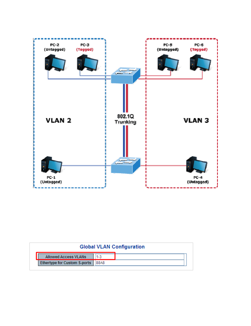
other switches within the same VLAN group. The screen in
Figure 4-6-12
appears.
Figure 4-6-12:
VLAN Trunking Diagram
Setup steps
1. Add VLAN Group
Add two VLANs – VLAN 2 and VLAN 3
Type 1-3 in Allowed Access VLANs column, the 1-3 is including VLAN1 and 2 and 3.
Figure 4-6-13:
Add VLAN 2 and VLAN 3
2. Assign VLAN Member and PVID for each port :
VLAN 2 : Port-1,Port-2 and Port-3
See also other documents in the category Interlogix Accessories communication:
- 600-1053-4 (12 pages)
- NX-590NE (38 pages)
- NX-591NE-GSM (16 pages)
- NX-592E (13 pages)
- Simon XT CDMA Module V4 (9 pages)
- Simon XT GSM Module V4 (10 pages)
- NX-548E (12 pages)
- NX-540E (32 pages)
- D1000 Series (10 pages)
- D1300 Series (11 pages)
- D1315 Series (10 pages)
- D1810 Series (8 pages)
- D2100 Series (10 pages)
- D2300CPS Series (10 pages)
- D7100 Series (8 pages)
- D7400 Series (10 pages)
- D7400RSH Series (10 pages)
- DE7100 Series (9 pages)
- DE7200M Series (8 pages)
- DE7300 Series (9 pages)
- DECT3000 Series (8 pages)
- DED2500 Series (9 pages)
- DT3000 Series (6 pages)
- D1200 Series (8 pages)
- D19100SHR Series (16 pages)
- D9100 Series (12 pages)
- MC250-4T/1CXT (25 pages)
- MC251-4P/1CXT (28 pages)
- MC250-4T Series (23 pages)
- MC251-4P/1S (27 pages)
- MC350-4T-2S (32 pages)
- MC352-4P-2S (31 pages)
- MCR200-1T/1CX (25 pages)
- MCR200-1T-1TW (23 pages)
- MC250-1T/1S (24 pages)
- MCR205-1T/1S User Manual (62 pages)
- MCR205-1T/1S Installation Guide (11 pages)
- MC201-1P/1FS (20 pages)
- MC355-1T/1S Installation Guide (13 pages)
- MC350-1T-2S (29 pages)
- MC352-1P/1S (29 pages)
- MC355-1T/1S User Manual (64 pages)
- MCR300-1T/1S (20 pages)
- MCR300-1T-2S (17 pages)
- MCR-R15 (14 pages)