Checkline TI-CMXDLP User Manual
Page 8
– 8 –
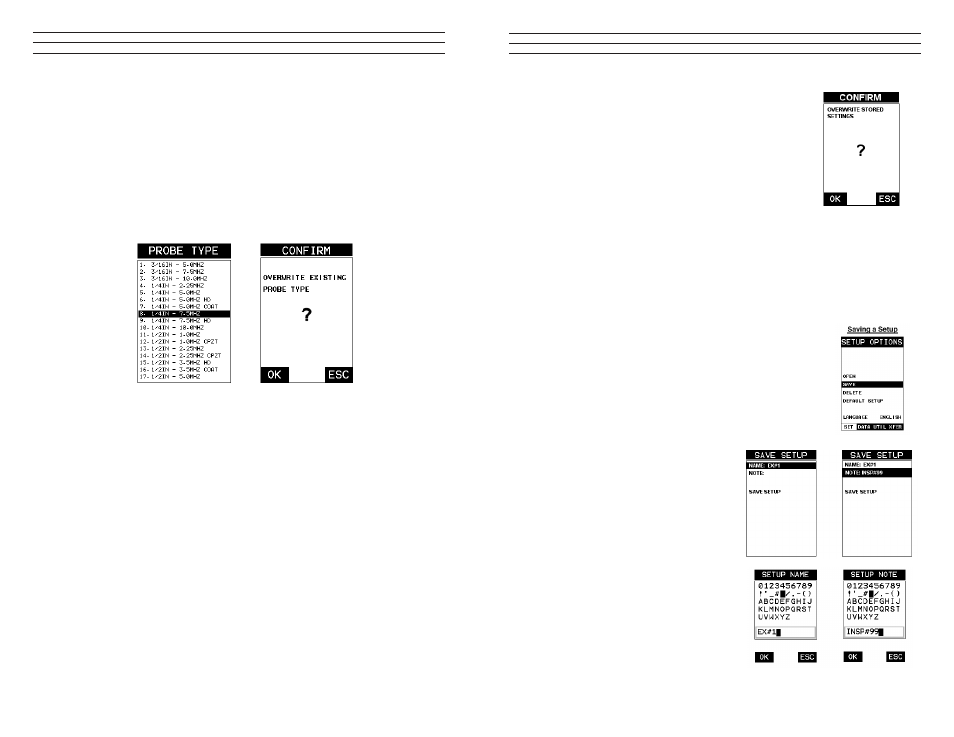
1. Press the OK or ESC keys to display the factory list of transducer types
(by diameter and frequency).
2. Press the UP and DOWN arrow keys to scroll through the transducer list until the
appropriate type is highlighted.
3. Press the ENTER key to select the transducer type and display overwrite existing
probe screen.
4. Press the OK key to overwrite the existing probe type with the newly selected probe
type. The zero probe screen will be displayed. Proceed to the zero probe section that
follows.
2.4 Probe Zero & Calibration
The next steps are to perform a probe zero and calibrate the TI-CMXDLP to the material
and transducer being used. If the sound velocity is unknown, the TI-CMXDLP can be
calibrated to a known thickness sample. This demo will briely explain both of the set
techniques. The TI-CMXDLP is equipped with two zero options:
1. Off Block Zero (Automatic Probe Zero): When this feature is enabled the
TI-CMXDLP will do an electronic zero automatically, eliminating the need for a
zero disk or block.
2. On Block Zero (Manual Probe Zero): When this feature is enabled the transducer
must be placed on the Probe Zero Disk (battery cover located on the top of the unit.
NOTE: Transducers of the same type will have very slight mechanical and electrical
variations. If it’s discovered that the linearity is off following an initial auto probe
zero and extreme accuracy is required, a manual zero should be performed followed
by an auto zero. This will adjust and eliminate any error. This is only required if
it’s discovered the transducer is non-linear following an initial auto probe zero. The
procedures are outlined as follows:
– 97 –
4. Use the UP and DOWN arrow keys to scroll through
the setups until the target setup is highlighted.
5. Press the ENTER key to activate the conirmation
screen.
6. Press the OK key to load the setup from memory.
7. Press the MEAS key to return to the measure screen.1
12.3 Saving a Setup
Once the TI-CMXDLP parameters and features have be adjusted for an application,
the user may elect to save these setting to a speciic setup location for future use. This
can potentially save time and reduce error between users. It is sometimes necessary to
rename a previously saved setup, or add additional comments about a particular setup.
The setup name may have been entered incorrectly, or the user needs to use the setup for
a completely different project. An inspector’s name or other comments about the project
may also be required for additional documentation purposes. The following procedures
outline the necessary steps for saving and editing a setup:
1. Press the MENU key once to activate the menu items tab.
Press the MENU key multiple times to tab right and the
ESC key multiple times to tab left until the SETUP menu
is highlighted and displaying the submenu items.
2. Use the UP and DOWN arrow keys to scroll through the
sub menu items until SAVE is highlighted.
3. Press the ENTER key to display the
Save Setup Parameters List Box.
4. Press the UP and DOWN arrow keys to
scroll the Name and Note parameters.
5. When the parameter to edit is
highlighted, press the ENTER key to
activate the Alpha Edit Box.
6. Use the UP, DOWN, LEFT, and
RIGHT arrow keys to scroll through
the characters, the ENTER key to
select characters, and the CLR key to
backspace through the characters, until
the Name or Note ields have been
edited.