Checkline TI-CMXDLP User Manual
Page 48
– 48 –
Adjusting the Range (B-Depth)
Once again, just to reiterate, the Range (B-Depth) + Delay (B-Start) equals the right
side of the screen. Therefore, the Range (B-Depth) is the overall area, from the delay,
that will be viewable on the screen. The TI-CMXDLP digitizer will round up from the
Range (B-Depth) that’s entered. Therefore, if the Range (B-Depth) is set at 1.0”, the
digitizer will round this value up to the next adjustment available. The procedures to
adjust the overall thickness range viewed Range (B-Depth) are outlined below:
1. Press the MEAS key once to
activate measure menu items.
Press the MEAS key multiple
times to move right and the
ESC key multiple times to move
left, until the WIDTH cell is
highlighted.
2. Press the UP, DOWN, LEFT,
and RIGHT arrow keys to scroll
the highlighted value.
3. Alternatively , press the ENTER
key to display the Digits Edit
Box.
4. Press the UP and DOWN arrow
keys to scroll the highlighted
value.
5. Press the LEFT and RIGHT
arrow keys to scroll the digit
locations.
6. Repeat steps 4 & 5 until the
WIDTH value is correctly
displayed.
7. Press the OK key to return to the
measurement screen, or ESC to
cancel entering the WIDTH.
8. Finally, press the MEAS key to
return to the measurement screen
and begin taking readings.
– 57 –
aluminum, stainless steel, and titanium. This can also be a function of using a low
frequency transducer, which are known to be inherently noisy off the initial pulse. The
start feature of the gate is also used in multiple echo modes to control measurements
between 2 or more echoes. As we saw in previous section,the threshold can be used
to control the sensitivity level, and used in combination with the width, control the
sensitivity over a speciic range.
Gate 2 & 3
These gate options will most commonly be used for multiple echo measurement modes,
to measure between 2 or more echoes ( E-E and E-EV). They are also handy to use in
a stand pulse echo mode, to create a pseudo time corrected gain feel. As the thickness
of the material increases, the signal amplitude of the relection decreases. Why not just
turn up the gain? Well, this is certainly something to consider, but is not always the
best answer. As the gain is increased, the noise level is also increased. At some point,
increasing the gain provides little or no beneit to the quality of the signal, and the
additional noise introduced makes things worse. By activating another gate, optimizing
the gain level, setting the thresholds, and adjusting the widths of the gates to cover
speciic thickness ranges, a tough application might not be so bad after all. These gates
have the following features set assigned to them; holdoff (delay), width, and threshold.
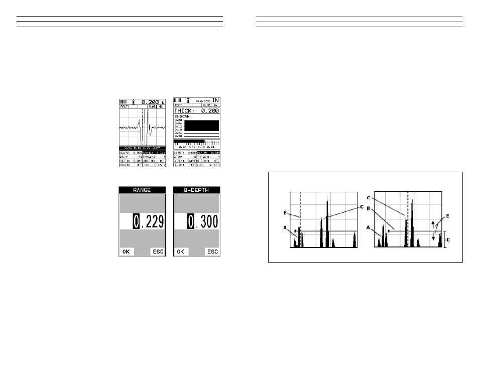
Noise
Blocked
Example of Surface or Transducer Noise
The diagrams above illustrate a typical surface noise condition. Refer to the Noise
diagram: (A) refers to the noise in front of the actual back wall signal (C). Notice the
start position of the gate. As a result, the TI-CMXDLP is detecting on the noise (A) as
shown at point (B). However, the true measurement should be taken at point (C). Given
the start, threshold, and gain levels, the amplitude from the noise is suficient enough
to cause the TI-CMXDLP to detect, or measure the noise rather than the true back wall
thickness.
Now refer to the Blocked diagram. The horizontal line at the top of (D), is GATE1. The
start of GATE1 has been moved just beyond the noise (A) to block the noise and detect
on the correct signal (C). Note: the TI-CMXDLP will only detect on signals that are