Checkline TI-CMXDLP User Manual
Page 51
– 51 –
3. Alternatively, press the ENTER key to display the
igits Edit Box.
4. Press the UP and DOWN arrow keys to scroll the
highlighted value.
5. Press the LEFT and RIGHT arrow keys to scroll the
digit locations.
6. Repeat steps 4 & 5 until the GAIN value is correctly
displayed.
7. Press the OK key to return to the measurement screen,
or ESC to cancel entering the GAIN.
The user can also access and adjust the gain from the tabbed menus. However, this
method is more tedious than making the adjustments using the Hot Menus. The
procedure using the tabbed menus is outlined below:
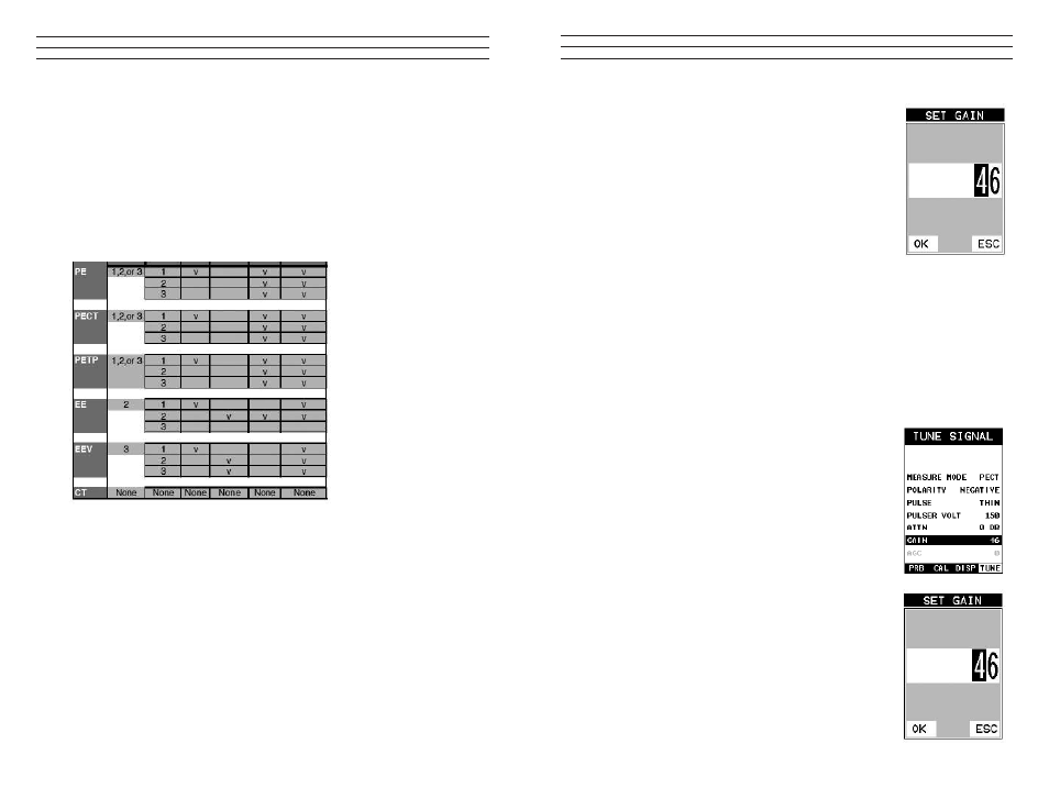
Adjusting the Gain using the Tabbed Menus
1. Press the MENU key once to activate the menu items tab. Press the MENU key
multiple times to tab right, and the ESC key multiple times to tab left, until the
TUNE menu is highlighted and displaying the submenu items
2. Use the UP and DOWN arrow keys to scroll through the
sub menu items until GAIN is highlighted.
3. Press the LEFT and RIGHT arrow keys to scroll the
value. When the correct Gain is being displayed, proceed
to step 8 .
4. Alternatively, press the ENTER key to display the
Digits Edit Box.
5. Press the UP and DOWN arrow keys to scroll the
highlighted value.
6. Press the LEFT and RIGHT arrow keys to scroll the
digit locations.
7. Repeat steps 5 & 6 until the Gain value is correctly
displayed.
8. Press the OK key to set the Gain and return to the menu
screen, or ESC to cancel entering the Gain.
9. Finally, press the MEAS key to return to the
measurement screen and begin taking readings.
– 54 –
7.6 Understanding the features of the Gate
IMPORTANT: It is recommended to spend some time in this section. The sections that
follow are procedures for using the features associated with the Gates, in some way.
There are 3 gates in the TI-CMXDLP, and as a result, operating and setting them up
can become somewhat convoluted, to say the least. However, a thorough understanding
of the functionality presented in this section, will reveal how easy they actually are to
operate overall. The following diagrams illustrate the features of all 3 gates,according to
the measurement mode selected:
NOTE: This is a general overview and should be referred to in conjunction with the
detailed feature sections that follow.
In diagram 1, the gates have been associated with the measurement modes, along with
the features available to every gate. For example, echo-echo mode (EE) has 2 gates
available, while echo-echo verify (EEV) has 3. These gates have been designed to work
in order, from 1 to 3, and cannot be used any other way. Therefore, the user must be
using gate 2 before they can activate and use gate 3.
NOTE: Gate 1 is on at all times, as a gate must be activated to get a measurement. Each
gate has a given set of features to ine adjust the settings of the gate. Let’s have a look
at the feature set:
Start (Gate1):
This feature is only available to gate 1, and determines the start value of the left side
of the gate. For example, if there’s a great deal of noise from the initial pulse, or in the
material, the gate can be moved to the right of the noise and block the unwanted noise.
Gates 2 and 3 will automatically start from the end of gate 1, or from a detection found
inside of the boundaries of gate 1. Therefore, we use a hold-off delay as a start feature
for gates 2 and 3. See Diagram 2.