Checkline TI-CMXDLP User Manual
Page 47
– 47 –
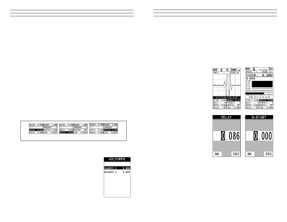
Setting the Delay (B-Start)
The Delay (B-Start) represents the left side of the display, and can be adjusted to start
at any thickness value within the overall range of the TI-CMXDLP. The value the Delay
(B-Start) is set too, is the minimum thickness value that will be displayed on the screen
NOTE: Once the delay is set, it will remain the same for the views: Digits, RF, RECT.
However, in B-Scan view, the B-Start is an independent setting from Delay, and allow
the user to store two independent settings respectively. The procedures to adjust the
Delay (B-Start) are outlined below:
1. Press the MEAS key once to
activate measure menu items.
Press the MEAS key multiple
times to move right and the
ESC key multiple times to
move left, until the DELAY
cell is highlighted
2. Press the UP, DOWN, LEFT,
and RIGHT arrow keys to
scroll the highlighted value.
3. Alternatively , press the
ENTER key to display the
Digits Edit Box.
4. Press the UP and DOWN
arrow keys to scroll the
highlighted value.
5. Press the LEFT and RIGHT
arrow keys to scroll the digit
locations.
6. Repeat steps 4 & 5 until the
DELAY value is correctly
displayed.
7. Press the OK key to return to the measurement screen, or ESC to cancel entering the
DELAY.
8. Finally, press the MEAS key to return to the measurement screen and begin taking
readings.
– 58 –
located inside the dimensions of GATE1 (B). Therefore, the TI-CMXDLP cannot
see (A)at all, with respect to the starting point of (B). Also notice, the position of the
threshold level with respect to the baseline (D), which represents the sensitivity setting
of the threshold. Extreme sensitivity is indicated by the bottom of the range(D) at the
baseline, and less sensitivity indicated by the top of the range at (D).Therefore, the
vertical height of GATE1 from the baseline, is the threshold level. The threshold level
can be increased to decrease sensitivity, or visa versa.
If the threshold level was increased in the Noise diagram, so that the vertical position of
GATE1 was higher than the amplitude of the noise (A), the TI-CMXDLP would have
detected on the true back wall (C). Alternatively, if the gain level was decreased, the
signal amplitude of the noise (A) would have decreased below the threshold level,and
the TI-CMXDLP would have also detected the true back wall (C). This example brings
all the ine adjustments into consideration, and demonstrates the versatility of having a
fully functional scope rather than a basic digital thickness gauge.
The procedures to adjust all of the features associated with the Gates are outlined below:
NOTE: This is a combined procedure that works the same for any of the features
associated with the gates, regardless of which feature and gate number that is being
adjusted. Therefore (? ) = Gate1, Hold-Off, and Width respectively. Finally, the
illustrations may not be applicable to the exact feature being adjusted, but the concepts
relevant.
Adjusting the Features of the Gates Using the Hot Menus
1. Press the MEAS key once to activate measure menu items. Press the MEAS key
multiple times to move right and the ESC key multiple times
to move left, until the (? ) cell is highlighted.
2. If the correct (? ) is displayed, press the UP, DOWN,
LEFT, and RIGHT arrow keys to scroll the highlighted
value.
3. Alternatively, if the correct (? ) is not being displayed,
press the ENTER key to display the List Box.
4. Use the UP and DOWN arrow keys to scroll through the
List Box items until the correct (? ) is highlighted.
5. Press the MEAS key to return to the measure screen and
Hot Menu items.
Gate
Holdoffs
Widths