Checkline TI-CMXDLP User Manual
Page 37
– 37 –
6.3 Material Calibration
In order for the TI-CMXDLP to make accurate measurements, it must be set to the
correct sound velocity of the material being measured. Different types of materials have
different inherent sound velocities. For example, the velocity of sound through steel
is about 0.233 inches per microsecond, versus that of aluminum, which is about 0.248
inches per microsecond. If the gauge is not set to the correct sound velocity, all of the
measurements the gauge makes will be erroneous by some ixed percentage.
The One Point calibration is the simplest and most commonly used calibration method
—optimizing linearity over large ranges. The Two Point calibration allows for greater
accuracy over small ranges by calculating the probe zero and velocity. The TI-CMXDLP
provides four simple methods for setting the sound-velocity outlined below:
Using A Known Material Velocity
1. Press the MENU key once to activate the menu items tab.
Press the MENU key multiple times to tab right and the
ESC key multiple times to tab left until the CAL menu is
highlighted and displaying the submenu items.
2. Use the UP and DOWN arrow keys to scroll through the
sub menu items until VELOCITY is highlighted.
3. Press the ENTER key to display the Digits Edit Box.
4. Press the UP and DOWN arrow keys to scroll the
highlighted value.
5. Press the LEFT and RIGHT arrow keys to scroll the digit locations.
6. Repeat steps 4 & 5 until the velocity number is correctly displayed.
7. Press the OK key to set the velocity and return to the menu screen, or ESC to cancel
entering the velocity.
8. Finally, press the MEAS key to return to the measurement screen and begin
taking readings.
Using A Known Material Thickness
Sometimes the sound velocity of a material is unknown. In this case a sample with one
or two known thicknesses can be used to determine the sound velocity. As previously
discussed, the TI-CMXDLP has a one or two point calibration option. The one point
calibration option is most suited for linearity over large ranges, as noted above. The user
should also consider calibrating on high side of the intended measurement range, when
using the one point option, minimize overall error. For example, if the measurement
– 68 –
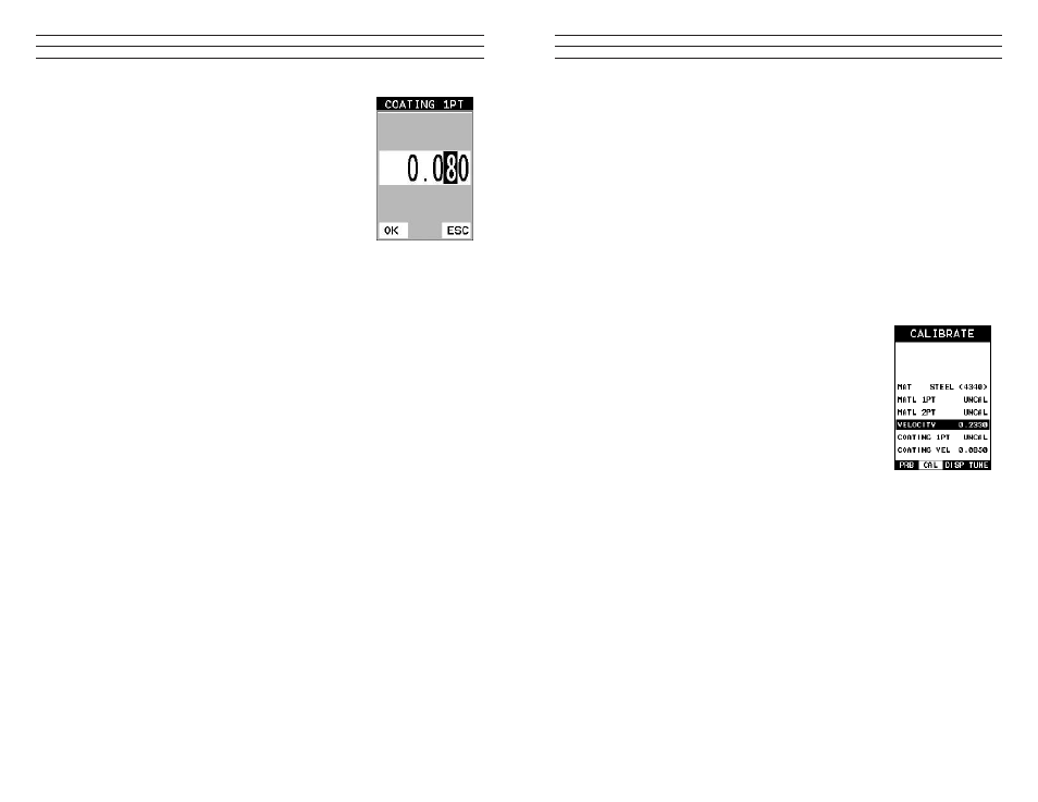
3. Use the UP and DOWN arrow keys to scroll through the
sub menu items until COATING 1PT is highlighted.
4. Press the ENTER key to display the Digits Edit Box.
5. Press the UP and DOWN arrow keys to scroll the
highlighted value.
6. Press the LEFT and RIGHT arrow keys to scroll the
digit locations.
7. Repeat steps 5 & 6 until the known thickness value is
correctly displayed
8. Press the OK key to calculate the velocity and return to the menu screen, or ESC to
cancel the coating one point calibration.
9. Finally, press the MEAS key to return to the measurement screen and begin taking
readings.
NOTE: CHECK YOUR CALIBRATION! Place the transducer back on the calibration
point. The coating thickness reading should now match the known thickness. If the
thickness is not correct, repeat the steps above.
9.5 Introduction to Coating Measurement (CT)
In the previous sections we’ve discussed how to setup and use the coating feature for
use in conjunction with material thickness for law and pit detection. The TI-CMXDLP
also has the capability to be used for general coating measurements. This measurement
mode is called Coating (CT) and can be enabled using the same methods as described in
a previous section above.
When the Coating Only (CT) mode is enabled, a two point calibration on the coating
samples must be performed. This is to ensure linearity over the coating measurement
range will be achieved.
IMPORTANT NOTE: If coating measurements will be made with the coating applied
to a metal surface, the calibration must be done in the same manner, with the samples
coupled to a metal surface. However, if the coating will be measured as a stand alone
material, the calibration must be performed the same way.
9.6 Two Point Coating Calibration (CT)
Known Thickness
The following section will demonstrate the two-point coating calibration procedure.
This example demonstrates a coating thickness range of .040” to .120” (1 to 3mm) as
follows:
NOTE: It’s always handy to carry a set of mechanical calipers to use in conjunction
with the TI-CMXDLP for calibration in the ield: