Checkline TI-CMXDLP User Manual
Page 31
– 31 –
measured without having to remove the coating prior to measuring. Users will often use
pulse echo mode and echo-echo mode in conjunction when performing inspections on
coated materials.
Thru coating measurements require special high damped transducers. The most common
transducers are the 3.5, 5, and 7.5 MHz hi-damped transducers. These transducers are
suitable for use in both pulse-echo and echo-echo modes. This conveniently enables the
user to accurately measure overall material thickness using the thru Coating mode, and
then conveniently switch to pit detection mode without changing transducers. The ¼”
5 MHz hi-damped transducer is the most commonly used transducer for standard thru
coating applications.
Coating Only
The coating only mode should be used when the application calls for coating
measurements only and the user is not interested in the thickness of the material the
coating has been applied to. This mode can also be used as a stand alone coating
thickness gauge, where the coating has not been applied to another material surface. An
auto identiied coating probe must be attached to the TI-CMXDLP in order to enable
this mode.
Thin materials
Use pulse echo mode and a high frequency transducer for these types of applications.
The most common transducers are the 7.5 MHz and 10 MHz models with extra
resolution. The higher frequencies provide greater resolution and a lower minimum
thickness rating overall.
High temperature
Use and select a special 2.25 MHz and 5 MHz High temperature transducer for these
types of applications. Both pulse-echo and echo-echo modes will also work for these
applications. However, echo-echo mode will eliminate error caused by temperature
variations in the delay line of the transducer.
Noisy Material
Materials such as titanium, stainless steel, and aluminum may have inherent surface
noise issues. This is a signal that appears at the surface of the material when using a
dual element delay line probe. Select a higher frequency transducer to reduce this
oise – 7.5 MHz and higher for better resolution.
Restricted access
Measuring materials with extreme curvatures or restricted access, higher frequencies
with smaller diameters should be considered. The smallest diameter uses 3/16”crystals
with a contact area of .250”. Custom transducers are available on request.
– 74 –
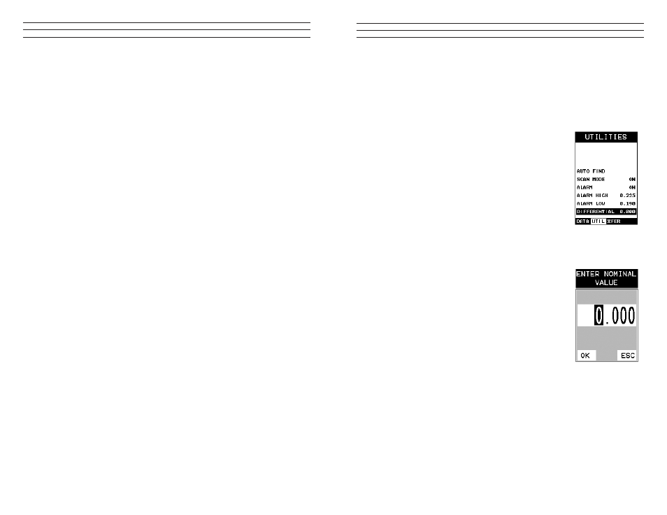
10.4 Differential Mode
The Differential Mode of the TI-CMXDLP provides the user with the ability to set
a nominal value, according to what the expected thickness should be, and measure
the+/- difference from the nominal value entered. This feature is typically used in QA,
incoming inspections on pipes, plate stock, coils, etc. The steps below outline how to
enable and enter the nominal value to use this feature:
Toggle Differential Off
1. Press the MENU key once to activate the menu items
tab. Press the MENU key multiple times to tab right, and
the ESC key multiple times to tab left, until the UTIL
menu is highlighted and displaying the submenu items.
2. Use the UP and DOWN arrow keys to scroll through the
sub menu items until DIFFERENTIAL is highlighted.
3. Use the LEFT and RIGHT arrow keys to toggle the
DIFFERENTIAL on. A value will appear to the right of
DIFFERENTIAL.
4. Continue on to the next section “Setting the Differential Value”.
Setting the Differential Value
1. Assuming DIFFERENTIAL has been enabled
and a value is being displayed to the right of the
DIFFERENTIAL label, press the ENTER key to display
the Digits Edit Box.
2. Press the UP and DOWN arrow keys to scroll the
highlighted value.
3. Press the LEFT and RIGHT arrow keys to scroll
the digit locations.
4. Repeat steps 2 & 3 until the DIFFERENTIAL value
is correctly displayed.
5. Press the OK key to set the DIFFERENTIAL value
and return to the menu screen.
6. Finally, press the MEAS key to return to the
measurement screen and begin taking readings.