Checkline TI-CMXDLP User Manual
Page 20
– 20 –
PULSER VOLTAGE: This feature offers a 50 volt cut/boost to the pulser. The standard
setting is 150 volts. This enables the TI-CMXDLP to offer greater penetration for
dificult material types, or increased resolution on noisy materials. Refer to section 10.3.
DAMPING: (color version only) – Provides the user with multiple input impedances to
match the impedance of the transducer, and optimized overall transducer performance.
Refer to section 10.8.
ATTN: This feature is a 20dB attenuator, as well as a 20dB ampliier. The primary
purpose is to is to offer further lexibility to the TI-CMXDLP , by either cutting or
boosting signal strength. In instances where the 60 dB range is not enough, or too
much, this feature allows you to increase/decrease the ampliier strength by a power
of 10 or(20dB). The standard setting is zero, which is an arbitrary value at a constant
attenuation. The attenuation value is added to the gain value. Therefore, if the attenuator
is increased to 20dB, this value is added to the value of the gain setting. Refer to section
10.4.
GAIN: The TI-CMXDLP has 100dB gain range from (-30 to 70 dB), used in
conjunction with the attenuator feature above. This feature is used to increase/decrease
the power or amplitude of the signal. This might easily be considered as similar to
turning the volume up or down on a stereo receiver. Refer to section 7.4.
AGC: This an automatic gain control used in E-E (echo-echo), and E-EV (echo-echo
verify). The TI-CMXDLP is equipped with an automatic gain control when operating
in -E(echo-echo), and E-EV (echo-echo verify) modes only. This feature automatically
increases/decreases the power or amplitude of the signal, to an optimal input to output
signal ratio. This might easily be considered as similar to turning the volume up or
down on a stereo receiver. Alternatively, the AGC can be manually controlled. The
TI-CMXDLP is equipped with manual override, using an arbitrary range of 1 to 20
clicks. The higher the number the better the dynamic gain range, and visa versa. Refer to
section 7.4.
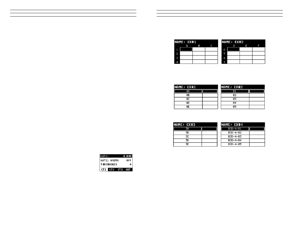
3.6 GT1 – Menu
GATE1: Gates allow the user to view a speciic
measurement range, or sections of the waveform, and
ignore others. The Gate1 feature adjusts the start of the
gate, according to time/distance. Gate 1 can be used
in all pulse-echo and echo-echo measurement modes.
Refer to section 7.6.
GATE1 WIDTH: This feature allows the user to set the overall width of the gate, in
terms of distance, from the starting value of Gate1. Refer to section 7.6 for further info.
THRESHOLD1: Enables the user to set the sensitivity level of Gate1. The amplitude
of the signal must reach or exceed the threshold level before a measurement is
detected. Refer to section 7.6.
– 85 –
Grid File Formats
Sequential Log Formats
IMPORTANT NOTE: For the duration of this chapter, all references to GRIDS and
SEQ LOGS should be considered synonymous with references to FILES.
11.2 CREATING A NEW GRID OR SEQUENTIAL LOG (FILE)
IMPORTANT NOTE: This entire section is a step by step guide to successfully create
a grid or sequential log. The instructions must be used in the sequential order speciied,
as follows: