Checkline TI-CMXDLP User Manual
Page 43
– 43 –
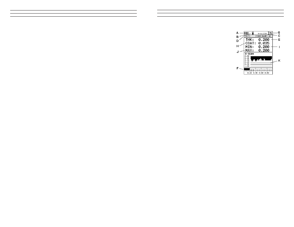
B-Scan.
The B-Scan displays a time based cross section
view of test material. This view is commonly
used to display the contour of the blind, or
underside, surface of a pipe or tank application.
It is very similar to a ish inder. If a law or pit
is located during a scan, the B-Scan will draw
the pit on the screen. The solid black rectangle
in the diagram at location K represents the cross
section, or side view of the material. The B-Scan
view draws at a rate of 7 seconds per screen
from right to left. Also notice at location K, the
pits and corroded bottom surface of the material.
It’s important to note that the measurement range on the display be set wide enough,so
that the maximum thickness of the material can be viewed on the display. Using the
diagram above, if the material thickness was actually 1.75”, the underside of the
material would not be viewable according to the current range at 0.00” – 1.00”. All the
user would see is a black screen from 0.00” – 1.00” with no view of the bottom contour
at 1.75”. The following is a list of the viewable features on the display:
A. Repeatability/Stability Indicator – This indicator should be commonly used
in conjunction with the digital thickness values displayed. When all the vertical
bars are fully illuminated and the last digit on the digital thickness value is stable,
the TI-CMXDL is reliably measuring the same value 3 to 200 times per second,
depending on which measurement mode and features are enabled.
B. Battery Icon – Indicates the amount of battery life the TI-CMXDL has remaining.
C. Velocity – The material velocity value the TI-CMXDL is currently using or
calibrated for. Displayed in either English or Metric units, depending on what units
the gauge is set for.
D. Feature Status Bar – Indicates the features currently enabled and in use in the
following order:· Measurement Mode (P-E, PECT, PETP, E-E, COAT)·
Differential Mode (ON/OFF)· High Speed Scan Mode (ON/OFF)· Alarm Mode
(ON/OFF/AUDIBLE)· Gain Setting (VLOW, LOW, MED, HI, VHI)
E. Digital Material Thickness Value – Smaller font size Smaller font size when the
B-Scan display view is enabled.
F. Scan Bar – Another view of material thickness in a delection style horizontal bar.
This is another visual tool that would enable the user the ability to see thickness
changes during high speed scans from laws and pits.
G. Units – The current measurement units being used (English, Metric).
– 62 –
The adjustment considerations in the example above will typically be used for
all thrupaint applications respectively. In some applications the hold -off may be
suficient,while a gain(AGC) or thresholds adjustment will solve the problem. A
similarprocess of elimination should be considered for all thru paint applications.