Checkline TI-CMXDLP User Manual
Page 24
– 24 –
3.17 Arrow Keys
The Arrow Keys are used to navigate through the menus, increase/decrease values,and
toggle speciic function keys.
3.18 ENTER key
The ENTER key is used in the menu selection process to activate list
and edit boxes, display and save measurements to grid or sequential iles
locations.
3.19 MULTI MODE Key
The MULTI MODE key opens a measurement mode screen, listing all
the modes that are available to the transducer speciically selected, or auto
detected. The modes can be all or a combination of the entire set of modes
the TI-CMXDLP offers, depending on which transducer is being used as
follows: Coating Off (P-E), Coating On (PECT),Temp Comp (PETP), Thru
Coat (E-E), Thru Coat Verify (E-EV), and Coating Only(CT).
3.20 ON/OFF Key
The ON/OFF key simply powers the unit either ON or OFF. Note: Unit will
automatically power off when idle for 5 minutes. All current settings are
automatically saved prior to powering off.
3.21 Top & Bottom End Caps
The top & bottom end panels are where all connections are made to the TI-CMXDLP.
The diagram above shows the layout and description of the connectors:
Transducer Connectors
The transducer connectors, and battery cover/Probe Zero Disk are located on the
TI-CMXDLP’s top end cap. The transducer connectors are of type Lemo“00”.
NOTE: There is no polarity associated with connecting the transducer to the
TI-CMXDLP.
–81 –
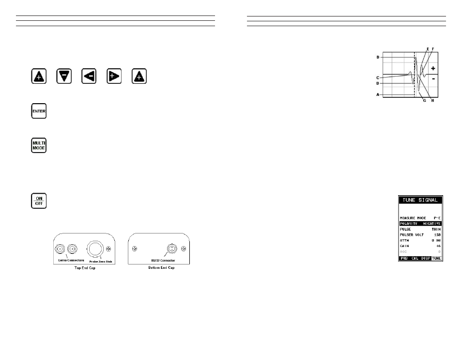
Notice the +/- positions in the diagram. The
positive phase is everything above the horizontal
center line, and the negative everything below
the center line. The TI-CMXDLP uses a zero
crossing (lank) method for detection. Therefore,
the detect line (A) is represented by the broken
vertical dotted line, and is currently detecting
on the negative portion of the waveform (B) at
the zero crossing (C). The signal amplitude (B)
is shown as the negative vertical height at (B) in
the diagram. Refer to the height of the second
negative peak at (G). It’s clear that the amplitude of (G) is much greater than that of
(B). Therefore, if the user was measuring thick attenuative material, and the amplitude
of (B) decreased substantially, the TI-CMXDLP would lose the irst cycle (B) and peak
jump to the second cycle (F). The detect (A), would move to (F), resulting in incorrect
measurements. If the user were to select the positive phase in the diagram above, the
detect would measure at (H). (A) would move to (H). Notice the height of (D) with
respect to the height of (E) in the diagram.
If the user was measuring thick attenuative material using this phase, the signal (E) will
certainly be lost long before (D). Therefore, the positive phase is a much better choice in
the diagram above.
Toggle Polarity (+/–)
NOTE: Before toggling the Polarity, the TI-CMXDLP
should be set to the RF display view option. The RF view
will give the user the best opportunity to correctly view the
positive and negative cycles of the waveform. Please refer to
section 7.1 for information on selecting the Display Views.
1. Press the MENU key once to activate the menu items
tab. Press the MENU key multiple times to tab right, and
the ESC key multiple times to tab left,until the TUNE
menu is highlighted and displaying the submenu items.
2. Use the UP and DOWN arrow keys to scroll through the
sub menu items until POLARITY is highlighted.
3. Use the LEFT and RIGHT arrow keys to toggle the
POLARITY negative or positive.
4. Press the MEAS key to return to the measurement
screen and begin taking readings.
IMPORTANT: Be sure to do a Probe Zero after changing
the polarity!