Checkline TI-CMXDLP User Manual
Page 49
– 49 –
Adjusting the B-Scan Speed (color version only)
The color version of the TI-CMXDLP has the
capability to adjust the scrolling speed of the time
based B-Scan displayed in the gauge. The procedures
to adjust the speed are outlined below:
1. Press the MENU key once to activate the menu
items tab. Press the MENU key multiple times
to tab right, and the ESC key multiple times to
tab left,until the DISP menu is highlighted and
displaying the submenu items.
2. Use the UP and DOWN arrow keys to scroll
through the sub menu items until B-SCAN
SPEED is highlighted.
3. Use the LEFT and RIGHT arrow keys to scroll the speed from 0-10.
NOTE: 10 representing the fastest scroll time.
Once the appropriate speed is displayed, press the MEAS key to return to the
measurement screen and begin the B-Scan process.
4. Alternatively, press the ENTER key to display the Digits Edit Box.
5. Press the UP and DOWN arrow keys to scroll the highlighted value.
6. Press the LEFT and RIGHT arrow keys to scroll the digit locations.
7. Repeat steps 5 & 6 until the SPEED is correctly displayed.
8. Press the OK key to set the speed and return to the DISP menu., followed by
pressing the MEAS key to begin the B-Scan process.
9. Finally, press the MEAS key to return to the measurement screen and begin the
scanning process.
7.4 Gain
The gain, or ampliication of the return echoes, can be adjusted in the TI-CMXDLP
to accommodate a variety of applications. The setting of the gain is crucial in order to
obtain valid readings during the measurement process. Too much gain may result in
erroneous measurements, by detecting on noise rather than the actual material back wall
itself. Not enough gain may result in intermittent detection. It may also result in lack
of detection on internal laws, pits, or porosity. The gain can easily be compared to the
volume control of a home stereo system. If you turn it up too much, you can’t hear the
music clearly. If it’s turned down too much, you can’t hear it.
– 56 –
Activating the gates:·
Automatically:
The gates are automatically activated, when a measurement
mode is selected. Gate1 is active in all measurement modes.
These modes have been internally setup at the factory.
Therefore, if the user selects the Thru Coat (E-E) option, an
internal setup will be loaded, and 2 gates will automatically
be activated. This setup will work ine for the majority of all
common applications. The user has the ability to ine adjust
the gates settings, which will be further explained in the
sections that follow.·
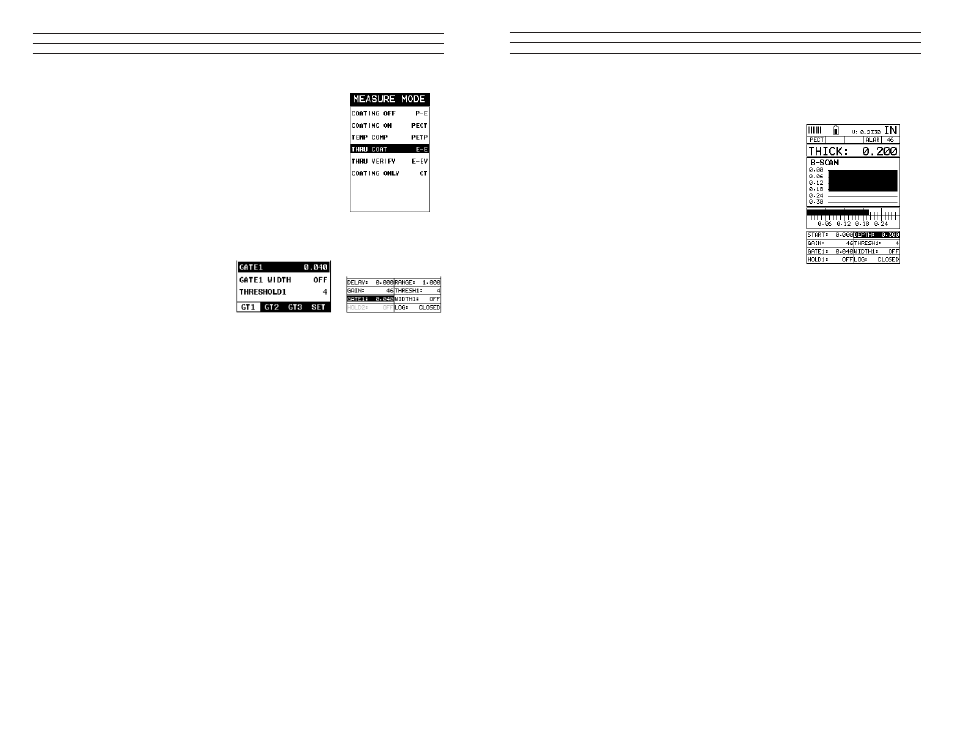
Manually:
The gates can also be activated
manually by using the Hot or Tabbed
menus. For example: If any of
the pulse echo modes (PE, PECT,
PETP), shown in diagram 1, have
been selected, only gate 1 will have
been activated from the factory
setup. However, the user may have
a requirement to activate and utilize
more than one gate, depending on the application.
7.7 Gates
The TI-CMXDLP is equipped with 3 gates, as explained in the previous section. One
gate is active at all times in every measurement mode, with the exception of coating
mode. These gates are full featured and completely adjustable. They can be ine tuned
by the user to accommodate a variety of application scenarios. Diagram 1 in the
previous section outlines the gates and features available for all measurement modes.
Refer to the previous section for additional information. These features are described in
more detail below:
NOTE: In order to adjust the gates they must be activated. The gates are automatically
activated depending upon the measurement mode selected. If a gate is inactive, it will
be grayed out in the hot and tabbed menus. The explanations thatfollow, assume that the
proper measurement mode has been selected. Refer to section 5.2 for more information
on selecting measurement modes.
Gate 1
Is used in all measurement modes, and has the following features assigned to it;start,
width, and threshold. A gate can be used to overcome a great deal of application
scenarios. Surface noise, for instance, close to the initial pulse can cause the erroneous
measurements as the transducer receives relections from the noise. By adjusting the
start position of the gate, the noise can be blocked and eliminated. This is typical in
Tabbed Menu
Hot Menu