Checkline TI-CMXDLP User Manual
Page 14
– 14 –
2.7 Measure
The TI-CMXDLP is now ready to measure. There are four different measurement view
options, each with a speciic purpose – Digits, RF, RECT, & B-Scan. The below outline
how to toggle between the different view mode options:
Selecting the Measurement View Option
1. Press the MENU key once to activate the menu items
tab. Press the MENU key multiple times to tab right and
the ESC key multiple times to tab left until the DISP
menu is highlighted and displaying the submenu items.
2. Use the UP and DOWN arrow keys to scroll through the
sub menu items until VIEW is highlighted.
3. Use the LEFT and RIGHT arrow keys to scroll the view
options.
4. Once the view is displayed, press the MEAS key to
return to measurement mode.
DIGITS: Displays the digital thickness value using a large font size. This view is useful
when the TI-CMXDLP is being used as a basic thickness gauge.
RF: Displays the actual waveform signal, much like an oscilloscope, from the relection
of the opposite surface, pit, law, crack or void. This view shows both the positive and
negative peaks, and is often used to ine tune the scope settings, prior to inspection
RECT: Displays a half waveform signal, either positive or negative, from the relection
of the opposite surface, pit, law, crack or void. The user can select the polarity or
“phase” displayed. This is typically determined by irst using RF view to select the most
optimal polarity “phase”, to ine tune the scopes settings. The RECT view is commonly
used as the primary “law detection” view.
BSCAN: The Time Based B-Scan provides the user with a cross sectional view of the
material being tested. This mode is useful when there is concern regarding the proile of
the blind surface. This can also be a useful view when scanning for pits and laws.
Once the view has been selected according to the application requirements, the Delay
and Range of the screen will potentially need to be adjusted, if the view has been set to
RF or RECT. Alternatively, if BSCAN was selected, the B-Start and B-Depth settings
will need to be adjusted. These settings serve the same purpose,with only differences
in terminology. The Delay the same as B-Start, and the Range is the same as B-Depth.
Therefore, these items will be grouped together for the duration of this manual, as
follows: Delay (B-Start) and Range (B-Depth). Use the following steps to adjust these
settings directly from the measurement screen as follows:
NOTE: The Delay (B-Start) and Range (B-Depth) are also used to adjust the parameters
of Scan Bar.
– 91 –
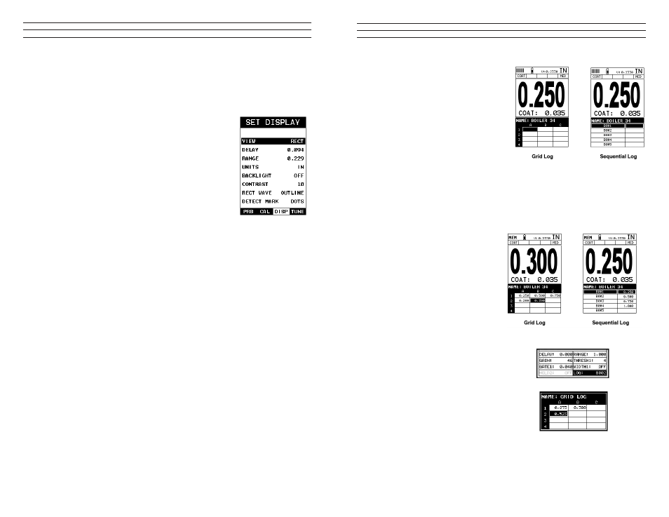
1. Press the UP, DOWN, LEFT,
and RIGHT arrow keys to scroll
the target cell cursor to the desired
storage location.
2. Press the ENTER key to save the
current reading in the highlighted
cell location. It’s as simple as that!
3. Press the MEAS key to hide the
GRID/SEQ View Box, or ENTER
to display it as necessary.
Note: Once the ile is open, it will remain open until it’s closed or another ile is opened
by the user. If the gauge is powered off, the TI-CMXDLP will automatically open
the ile when powered on. Simply press the ENTER key to display the ile from the
measurement screen.
11.4 Viewing stored readings & A/B Scans
It is sometimes necessary to
go back and view the stored
readings and B-Scans using the
TI-CMXDLP without a PC. The
following procedures outline this
process:
1. Press the MEAS key once to
activate measure menu items. Press
the MEAS key multiple times
to move right and the ESC key
multiple times to move left until the
LOG cell is highlighted.
2. Press the ENTER key to display
the Grid Log Box.
3. Press the UP, DOWN, LEFT, and
RIGHT arrow keys to scroll the stored
readings and corresponding display
view. Notice as the cursor is moved to a
different cell, the display will be updated
with the display view saved with the
reading. Readings stored in memory
are indicated by displaying a MEM in
the top left corner of the measurement
screen.