Checkline TI-CMXDLP User Manual
Page 35
– 35 –
6.2 Probe Zero
The next step is to perform a probe zero. The zero function is a very important and
necessary function that must be done prior to calibration. It should be done on a regular
basis. In fact, the TI-CMXDLP has been programmed to force this issue at regular
intervals during operation if it hasn’t been done. If the TI-CMXDLP is not zeroed
correctly, all the measurements taken may be in error by some ixed value. When the
TI-CMXDLP is using the auto zero (electronic zero), the TI-CMXDLP can be in any
measurement mode. However, when the manual zero is being used, the TI-CMXDLP
must be in pulse-echo mode in order to perform the zero. The TI-CMXDLP will also see
to it that this occurs by simply forcing the gauge into this mode when zero. Therefore,
if the TI-CMXDLP is in the echo-echo measurement mode and a manual zero is being
performed, the TI-CMXDLP will put the gauge into pulse-echo mode automatically
before performing the zero. While this is a very convenient feature of the TI-CMXDLP,
the user should be sure to check the measurement mode following calibration to be
sure the TI-CMXDLP is in the desired mode. The following steps outline both of these
techniques.
The TI-CMXDLP is equipped with two zero options:
1. Off Block Zero (Automatic Probe Zero) – When this feature is enabled the
TI-CMXDLP will do an electronic zero automatically, eliminating the need for a
zero disk or block.
2. On Block Zero (Manual Probe Zero) – When this feature is enabled the transducer
must be placed on the Probe Zero Disk (battery cover located on the top of the unit.
Both zero procedures are outlined as follows:
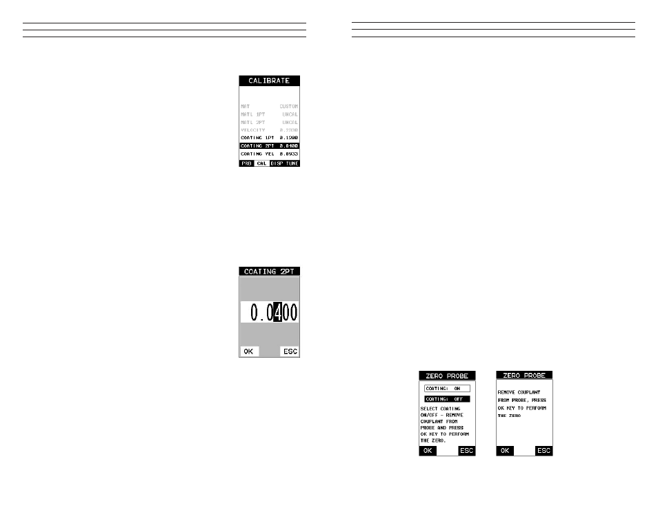
Performing an Auto Probe Zero (Off Block)
1. Be sure all couplant has been removed from the face of the transducer.
2. Press the OK key to perform the automatic probe zero, or ESC key to cancel the
zero operation.
3. The screens illustrated above will be briely displayed followed by the main
measurement screen. The TI-CMXDLP is ready to be calibrated.
Coating Probe Identified
Coating Probe Not Identified
– 70 –
Two Point Calibration
NOTE: Use the minimum coating sample for the two point
calibration.
1. Physically measure the thinner of the two samples of the
coating, as close as possible to the minimum expected
coating measurement range, using a set of calipers or a
digital micrometer.
VERY IMPORTANT: If coating measurements will be
made with the coating applied to a metal surface, the
calibration must be done in the same manner,with the
samples coupled to a metal surface. However, if the coating
will be measured as a stand alone material, the calibration
must be performed the same way.
2. Apply a drop of couplant on the transducer and place the transducer in steady
contact with the thinner of the two coating and samples. Be sure that the reading
is stable and the repeatability indicator, in the top left corner of the display, is fully
lit and stable. Press the MENU key once to activate the menu items tab. Press the
MENU key multiple times to tab right and the ESC key multiple times to tab left
until the CAL menu is highlighted and displaying the submenu items.
3. Use the UP and DOWN arrow keys to scroll through the
sub menu items until COATING 2PT is highlighted.
4. Press the ENTER key to display the Digits Edit Box.
5. Press the UP and DOWN arrow keys to scroll the
highlighted value.
6. Press the LEFT and RIGHT arrow keys to scroll the
digit locations.
7. Repeat steps 5 & 6 until the known thickness value is
correctly displayed.
8. Press the OK key to calculate the velocity and return to
the menu screen, or ESC to cancel the coating one point
calibration.
9. Finally, press the MEAS key to return to the
measurement screen and begin taking readings.
NOTE: CHECK YOUR CALIBRATION! Place the transducer back on both calibration
points. The coating thickness readings should now match the known thickness values of
each sample. If the thickness is not correct, repeat these steps above.