Checkline TI-CMXDLP User Manual
Page 28
– 28 –
V-Path Correction
Dual element delay line transducers have two piezoelectric
elements mounted at an angle on one end of the delay
line. One element is used for transmitting sound, while
the other element only receives sound. The two elements
and their delay lines are packaged in a single housing but
acoustically isolated from each other with a sound barrier.
This allows the transducer the ability to achieve very high
sensitivity for detecting small defects. Also, the surface
of the test material does not have to be as lat in order
to obtain good measurements. Dual element transducers
are normally used in pulse-echo mode for inding
defects,and in echo-echo mode for through coating measurements. Dual element delay
line transducers are usable over a range of 0.025 inches to 20 inches depending on the
material, frequency, and diameter. A limitation of dual element delay-line transducers
is the V shaped sound path. Because the sound travels from one element to another,
the time versus thickness relationship is non-linear. Therefore, a correction table in the
instruments software is used to compensate for this error.
Searching for small defects
Dual element delay line transducers are especially useful in searching for small defects.
In the pulse-echo mode with high ampliier gain, very small defects can be measured.
This is very useful during corrosion inspections overall. The dual element style
transducer will ind wall deterioration, pits, and any porosity pockets during tank and
pipeline inspections.
Echo-Echo Mode – Thru Coat (E-E)
The echo-echo mode measures between two relections. This technique is commonly
used to eliminate errors from surface coatings and also to make measurements in
multiple layered materials. The disadvantage is that two echoes are needed which
requires a much stronger echo (relection).
Echo-Echo Verify Mode – Thru-Verify (E-EV
)The echo-echo verify mode measures between 3
relections. Similar to E-E mode,this technique is
commonly used to eliminate errors from surface coatings
and also to make measurements in multiple layered
materials. The primary beneit of this mode,is that a
comparison is made, between the 2nd and 3rd echoes,
to verify that a peak jump has not occurred, providing
an additional level of conidence to the measurement.
The disadvantage is that 3 relections are needed which
requires the use of gates with controllable thresholds to
adjust for sensitivity over a given measurement range.
Dual Element Transducer
showing V-path of signal
Dual Element Transducer in
Echo to Echo mode
10.8 Damping (color version only)
The color version of the TI-CMXDLP has a built-in damping feature to control the
impedance input of the receiver. This enables the user the ability to match and optimize
the transducer for better signal quality at various frequencies. The available settings
are 50, 75, 100, 300, 600 and 1500 ohms. The procedures below outline the steps for
selecting an impedance setting, as follows:
Setting the Damping Value
1. Press the MENU key once to activate the menu items
tab. Press the MENU key multiple times to tab right, and
the ESC key multiple times to tab left,until the TUNE
menu is highlighted and displaying the submenu items.
2. Use the UP and DOWN arrow keys to scroll through the
sub menu items until DAMPING is highlighted.
3. Use the LEFT and RIGHT arrow keys to scroll through
the DAMPING values until the correct value is displayed
to the right of the DAMPING menu item.
4. Finally, press the MEAS key to return to the
measurement screen and begin taking readings.
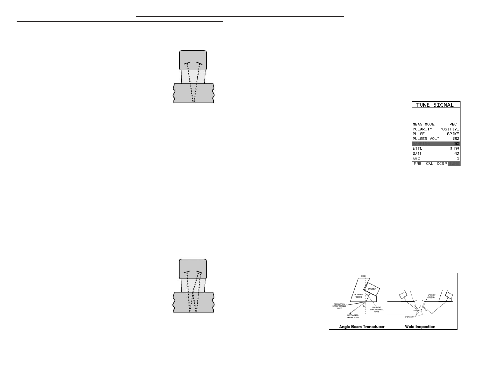
10.9 Introduction to Flaw Mode
The Flaw Mode feature was added to the TI-CMXDLP to provide inspectors with
a basic prove-up law detection mode using an angle beam transducer. This mode
enables inspectors to locate porosity, defects, inclusions, and cracks in a variety
of test materials. Angle beam transducers, are transducers attached to a delay line
wedge at speciic angles. Some of the more common angles are 45°, 60°, and 70°.
The sound wave is introduced into the test material at a speciic angle, and converted
from a longitudinal wave into a shear wave. The introduction at speciic angles enables
inspectors to steer the sound wave in a speciic direction according to the position and
location of speciic types of defects.
NOTE:
The TI-CMXDLP
AMOLED high speed
color version has a
120 Hz screen redraw
rate and exceeds
the speed found in
conventional digital
law detectors.
–77 –